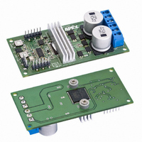
DB64 Cirrus Logic Inc, DB64 Datasheet - Page 2

DB64
Manufacturer Part Number
DB64
Description
DEMO BOARD FOR SA306-IHZ
Manufacturer
Cirrus Logic Inc
Series
Apex Precision Power™r
Type
MOSFET & Power Driverr
Specifications of DB64
Main Purpose
Power Management, Motor Control
Embedded
No
Utilized Ic / Part
SA306
Primary Attributes
3-Ph DC Motors
Secondary Attributes
12V Supply, 1kW Peak Power, 17A Peak Current, Board can Dissipate 7-9W
Input Voltage
5 V
Board Size
95.25 mm x 44.45 mm
Maximum Operating Temperature
+ 70 C
Minimum Operating Temperature
0 C
Product
Power Management Modules
Dimensions
95.25 mm x 44.45 mm
For Use With/related Products
SA306-IHZ
Lead Free Status / RoHS Status
Contains lead / RoHS non-compliant
Lead Free Status / RoHS Status
Lead free / RoHS Compliant, Contains lead / RoHS non-compliant
Other names
598-1488
© 2008 Cirrus Logic, Inc. All rights reserved. Cirrus Logic, Cirrus, the Cirrus Logic logo designs, Apex Precision Power, Apex and the Apex logo designs are
trademarks of Cirrus Logic, Inc. Other brand and product names may be trademarks or service marks of their respective owners.
INDUSTRIAl CoMPoNENTS
DIGITAl INTERFACE
The SA306-IHZ and the SA57-IHZ are both
designed to provide a seamless interface to either
a digital microcontroller (MCU) or DSP. The top
side and bottom side output FETs on these PWM
drivers can be individually controlled via direct
signals from the processor. Communication
between the driver and the processor includes
current sensing for each phase and is supplied as
individual inputs to the processor. Short circuit
protection and high temperature sensing is han-
dled as digital feedback signals. Communication
with the motor is the responsibility of the proces-
sor. In the case of a brushless motor, the proces-
sor changes the PWM signals to the top
transistors, as well as the ON-OFF signals to the
bottom transistors. This is based on the three
hall-effect feedback signals in the case of the
brushless motor which indicates position of the
rotor. For a brush motor, the PWM signals work
between the SA57-IHZ’s dual power stages and
the motor.
CyClE-By-CyClE CURRENT lIMIT
In typical motor control applications, the task of
controlling current is handled directly by the pro-
cessor or DSP. By using the SA306-IHZ or SA57-
IHZ as the system driver, current can be controlled
on a cycle-by-cycle basis in
real time for each motor
phase. This unique functional-
ity represents next generation
performance compared with
existing control
methodologies.
cycle-by-cycle current limit is
the ability to soft start the
motor by allowing the SA306-
IHZ or SA57-IHZ to handle the
inrush of start-up current. For
both of these ICs, this ability negates the
necessity to de-rate their current rating even at
5 A continuous or greater.
An extended benefit of
|
S A 3 0 6 - I H Z , S A 5 7- I H Z
SA57-IHZ Block Diagram: 2-phase driver (Out 1 and 2)
DEMoNSTRATIoN BoARDS AVAIlABlE
Fully assembled demonstration boards are avail-
able now for both the SA306-IHZ and the SA57-
IHZ to help with rapid prototyping. The DB63 is the
demo board for the SA57-IHZ, and the DB64 is set
up for the SA306-IHZ. Each board comes fully
assembled, including an evaluation unit of either
the SA57-IHZ or the SA306-IHZ.
TyPICAl APPlICATIoN
A GRADES AVAIlABlE
•
•
SA306-IHZ Block Diagram: 3-phase driver (Out A, B and C)
°
°
°
°
°
°
SA306-FHZ
SA57-FHZ
Specific performance enhancements
8 A continuous output current
Case temp range -40°C up to +125°C
Specific performance enhancements
8 A continuous output current
Case temp range -40°C up to +125°C
Product Bulletin 0218-0908-PB


