EVAL6599-400W-S STMicroelectronics, EVAL6599-400W-S Datasheet - Page 12
EVAL6599-400W-S
Manufacturer Part Number
EVAL6599-400W-S
Description
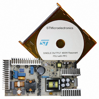
DEMO BOARD FOR L6599
Manufacturer
STMicroelectronics
Type
Power Factor Correctionr
Specifications of EVAL6599-400W-S
Main Purpose
AC/DC, Primary Side and PFC
Outputs And Type
3, Isolated
Power - Output
400W
Voltage - Output
200V, 5V, 3.3V
Current - Output
2A, 1A, 700mA
Voltage - Input
90 ~ 264VAC
Regulator Topology
Resonant
Board Type
Fully Populated
Utilized Ic / Part
L6563, L6599
Input Voltage
90 V to 264 V
Output Voltage
3.3 V to 200 V
Dimensions
132 mm x 265 mm
Product
Power Management Modules
Lead Free Status / RoHS Status
Lead free / RoHS Compliant
For Use With/related Products
L6599
Other names
497-5856
Available stocks
Company
Part Number
Manufacturer
Quantity
Price


Electrical test results
2.3
12/35
Figure 11. Overall efficiency versus input mains voltage at various output power
Resonant stage operating waveforms
Figure 12.
full load. The Ch1 waveform is the half-bridge square voltage on Pin 14 of L6599, driving the
resonant circuit. In the picture it is not evident, but the switching frequency is normally
slightly modulated following the PFC pre-regulator 100-Hz ripple that is rejected by the
resonant control circuitry. The Ch2 waveform represents the transformer primary current
flowing into the resonant tank. As shown, it has almost a sinusoidal shape. The resonant
tank has been designed (following the procedure presented in the application note AN2450)
to operate at a resonance frequency of about 120 kHz when the dc input voltage of the half-
bridge circuit is at 390 V (that is the nominal output voltage of the PFC stage).
The resonant frequency has been selected at approximately 120 kHz in order to have a
good trade off between transformer losses and dimensions.
The resonant tank circuit has been designed in order to have a good margin for ZVS
operation, providing good efficiency, while the almost sinusoidal current waveform allows for
an extremely low EMI generation.
Figure 13.
is at a light load (about 30 W) or not loaded at all. These two graphics demonstrate the
ability of the converter to operate down to zero load, with the output voltage still within the
regulation range. The resonant tank current has a triangular shape and represents the
magnetizing current flowing into the transformer primary side. The oscillation superimposed
on the tank current depends on the occurrence of a further resonance due to the parallel of
the inductances at primary side (the series and shunt inductances in the APR (all primary
referred) transformer model presented in AN2450) and the undesired secondary side
capacitance reflected at the transformer primary side.
and
shows some waveforms during steady state operation of the resonant circuit at
levels
Figure 14.
94%
93%
92%
91%
90%
89%
88%
87%
86%
85%
Eff[%]
80
shows the same waveforms as
120
400W
160
200W
Vin [Vrms]
200
70W
Figure
240
12, when the +200 V output
280
AN2492
Related parts for EVAL6599-400W-S
Image
Part Number
Description
Manufacturer
Datasheet
Request
R

Part Number:
Description:
EVAL BOARD FOR L6599
Manufacturer:
STMicroelectronics
Datasheet:

Part Number:
Description:
EVAL BOARD FOR L6599
Manufacturer:
STMicroelectronics
Datasheet:

Part Number:
Description:
DEMO BOARD FOR L6599
Manufacturer:
STMicroelectronics
Datasheet:

Part Number:
Description:
STMicroelectronics [RIPPLE-CARRY BINARY COUNTER/DIVIDERS]
Manufacturer:
STMicroelectronics
Datasheet:
Part Number:
Description:
STMicroelectronics [LIQUID-CRYSTAL DISPLAY DRIVERS]
Manufacturer:
STMicroelectronics
Datasheet:

Part Number:
Description:
BOARD EVAL FOR MEMS SENSORS
Manufacturer:
STMicroelectronics
Datasheet:
Part Number:
Description:
NPN TRANSISTOR POWER MODULE
Manufacturer:
STMicroelectronics
Datasheet:
Part Number:
Description:
TURBOSWITCH ULTRA-FAST HIGH VOLTAGE DIODE
Manufacturer:
STMicroelectronics
Datasheet:
Part Number:
Description:
Manufacturer:
STMicroelectronics
Datasheet:
Part Number:
Description:
DIODE / SCR MODULE
Manufacturer:
STMicroelectronics
Datasheet:
Part Number:
Description:
DIODE / SCR MODULE
Manufacturer:
STMicroelectronics
Datasheet:
Part Number:
Description:
Search -----> STE16N100
Manufacturer:
STMicroelectronics
Datasheet: