QW1 TechTools, QW1 Datasheet - Page 3
Specifications of QW1
Contents
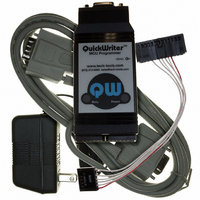
MCU Programmer with In-Circuit Serial Programming Cable and Optional GANG Adapters
For Use With/related Products
PIC Micro® MCU
For Use With
CBL-ICSP - CABLE PROG QUICKWRITER SERIALQW-4SSOP18 - ADAPTER QUICKWRITER 4GANG 18SSOPQW-4SSOP28 - ADAPTER QUICKWRITER 4GANG 28SSOPQW-4SO8/14W - ADAPT QUICKWRTR 4GANG 8/14SOIC WQW-4SO8/14N - ADAPT QUICKWRTR 4GANG 8/14SOIC NQW-4SOIC18 - ADAPTER QUICKWRITER 4GANG 18SOICQW-4ZIF18 - ADAPTER QUICKWRITER 4-GANG 18ZIFQW-4SOIC28 - ADAPTER QUICKWRITER 4GANG 28SOICQW-4PLCC44 - ADAPTER QUICKWRITER 4GANG 44PLCCQW-4ZIF40/28 - ADAPT QUICKWRITER 4GANG 40/28ZIFMP-ZIF14 - ADAPTER QUICKWRITER 14-PIN ZIFMP-SOIC8/14 - ADAPTER QUICKWRITER 8/14-SOICMP-SSOP18 - ADAPTER QUICKWRITER 18-SSOPMP-SSOP28 - ADAPTER QUICKWRITER 28-SSOPMP-14000 - ADAPTR QUICKWRTR PIC14000 28-PINMP-SOIC18 - ADAPTER QUICKWRITER 18-SOICMP-SOIC28 - ADAPTER QUICKWRITER 28-SOICMP-PLCC44 - ADAPTER QUICKWRITER 44-PIN PLCCMP-ZIF18/28 - ADAPTER QUICKWRITER 18/28PIN ZIFMP-ZIF40 - ADAPTER QUICKWRITER 40-PIN ZIF
Available stocks
Company
Part Number
Manufacturer
Quantity
Price
Company:

Part Number:
QW152
Manufacturer:
Laird Technologies IAS
Quantity:
135


DESIGNING FOR IN-CIRCUIT PROGRAMMING
In addition to the in-circuit support built into QuickWriter, there are still a few basic requirements
on the target to make it in-circuit programmable. The following defines the key issues related to
each signal involved in programming. The numbers in () are the in-circuit programming cable pin
numbers. Don’t let the lengthy discussion put you off; it really is pretty straightforward and most
targets require very little effort to make them in-circuit programmable. This discussion just seams
a little lengthy because we are providing the reasons for the requirements as well as the
requirements themselves. There is a condensed ‘design recommendations’ summary at the end.
MCLR/VPP (1)
HIGH VOLTAGE
This signal is driven to over 13V during programming. Your target must be able to tolerate this high
voltage on this signal. The PIC® MCU is designed to accept this voltage of course. However, anything
else attached to this pin probably will be damaged. You will need to isolate the MCLR/VPP line from
anything else in your target that could be damaged by the programming voltages. Possible devices include
a buffer (used to drive the reset to other devices), a power supply monitor/reset chip or a logic output used
to generate the reset in lieu of the standard RC setup.
Other Drivers
If you use logic to reset the chip in normal operation (rather than depend on the RC), then these drivers
must be isolated unless they can tolerate > 13V AND they do not actively drive (HIGH or LOW) the
MCLR line during programming.
Pull-ups
Any pull-up on MCLR must be 10K or larger. This prevents the programming voltage from forcing the
target power supply above its nominal 5V. It also allows QuickWriter to passively pull-down MCLR to a
reset state. If you have a smaller (stronger) pull-up, QuickWriter’s internal 1K pull-down will not be able
to pull MCLR to a valid low. QuickWriter will notice this and complain. If you have an existing target
with a strong pull-up and changing it to 10K is not an option, you can compensate by strengthening
QuickWriter’s pull-down proportionally. For example, if your pull-up is 4.7K (about 2x as strong), adding
a 1K pull-down between MCLR and ground on QuickWriter’s ICSP cable will double our pull-down
strength.
Capacitors
Although capacitors are generally not used on PICmicro® MCU reset circuits, but they can be and
sometimes are used. QuickWriter can tolerate up to 10uF of capacitance from MCLR to ground. The
voltage interlocks will wait until the capacitor is fully charged/discharged before continuing. NOTE that
this cap must be rated for > 13V!
Devices with Internal MCLR
Some devices require that MCLR be driven BEFORE VCC. This is very unusual and damaging to most
chips. For these devices, the programmer will drive 13V to the MCLR pin before applying power to the
target. If you have anything at all connected to MCLR, you should evaluate its tolerance to 13V EVEN
WHEN IT IS NOT POWERED. For these devices, you will want to diode isolate MCLR from VCC so
that MCLR does not attempt to power the VCC rail. Generally, place a diode in series with the MCLR
pull-up (anode to VCC) or completely isolate MCLR from VCC with a jumper.
Related parts for QW1
Image
Part Number
Description
Manufacturer
Datasheet
Request
R

Part Number:
Description:
ADAPT QUICKWRTR 4GANG 8/14SOIC N
Manufacturer:
TechTools
Datasheet:

Part Number:
Description:
ADAPT QUICKWRTR 4GANG 8/14SOIC W
Manufacturer:
TechTools
Datasheet:


Part Number:
Description:
ADAPTER QUICKWRITER 4GANG 18SOIC
Manufacturer:
TechTools
Datasheet:

Part Number:
Description:
ADAPTER QUICKWRITER 4GANG 44PLCC
Manufacturer:
TechTools
Datasheet:

Part Number:
Description:
ADAPTER QUICKWRITER 4GANG 28SOIC
Manufacturer:
TechTools
Datasheet:


