20C259 Tyco Electronics, 20C259 Datasheet - Page 3
20C259
Manufacturer Part Number
20C259
Description
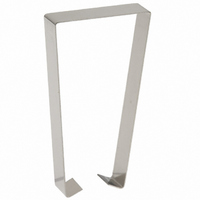
WIRE HOLD DOWN STRAP ALL POLES
Manufacturer
Tyco Electronics
Series
R10r
Datasheet
1.20C249.pdf
(6 pages)
Specifications of 20C259
Accessory Type
Clip, Hold Down
Associated Relay Series
None
Termination Style
Solder Terminal
Number Of Poles
All
For Use With/related Products
R10 Series
For Use With
PB812 - SOCKET 6 POLES IN LINEPB809 - SOCKET DP-2P IN LINE R10 SERIESPB806 - SOCKET 4POLE R10 SERIESPB804 - SOCKET 4POLE R10 SERIESPB803 - SOCKET DP-2P R10 SERIESPB805 - SOCKET DP-2P R10 SERIESPB799 - SOCKET 6P PC MNT 5TGR R10 SERIESPB641 - SOCKET SCREW TERM 6P R10 RELAYSPB640 - SOCKET SCREW TERM DP R10 RELAYS27E629 - SOCKET RELAY PCB R10 SERPB674 - SOCKET SCREW TERM 4P R10 RELAYSPB134 - R10 RELAY SOCKETS-TERMINALS
Lead Free Status / RoHS Status
Lead free / RoHS Compliant
Color
-
Lead Free Status / Rohs Status
Lead free / RoHS Compliant
Other names
20C259BULK
4-1393159-0
PB138
4-1393159-0
PB138


Dimensions are shown for
reference purposes only.
Our authorized distributors are more likely to stock the following items for immediate delivery.
R10-E1P2-115V
R10-E1P2-V700
R10-E1P4-115V
R10-E1P4-V700
R10-E1W2-V185
R10-E1W2-V700
R10-E1W4-V185
R10-E1W4-V700
R10-E1X2-115V
Ordering Information
1. Basic Series:
2. Case Style:
3. Terminals & Mounting:
4. Contact Style & Rating:
5. Number of Poles:
6. Coil (Refer to Coil Data Tables):
R10 = Relay with Form C contacts.
R10S = Super sensitive R10 (case and terminals E1 & E2 only, J coil adj. only).
E = Non-sealed polycarbonate cover.
R = Immersion cleanable, tape sealed plastic case (R10 only [Form C], terminal code 2 & 9 only [std. PCB]).
1 = Solder/plug-in terminals with #3-48 mounting stud.
2 = Printed circuit terminals (std.) .064” (1.62mm) clearance, 1.25” (31.75mm) seated ht.
6 = Side mounting plate with #6-32 stud, solder/plug-in terminals (#3-48 stud not included).
7 = Narrow (.04” [1.02mm] wide) printed circuit terminals .013” (.33mm) clearance, 1.2” (30.48mm) seated ht.
9 = Non-shouldered, narrow (.04” [1.02mm] wide) printed circuit terminals in a staggered arrangement (1 to 6 poles only).
1 = 1 pole.
2 = 2 pole.
3 = 3 pole.
Ratings are at 28VDC or 115VAC. Total load must not exceed 30A per relay.
† Use ungrounded frame for AC loads of 5A or greater. Max. ratings are 7.5A at 115VAC and 4A at 28VDC for coil codes S & J.
‡ Use ungrounded frame for AC loads of 5A or greater. Max. ratings are 5A at 115VAC and 3A at 28VDC for coil codes S & J.
AC Voltage (available on R10 only)
Specify nominal coil voltage followed by V (example: 24V).
R10
R10S
No ground or stud included. Not available on R10S.
V, Q, S & J Coil Adjustment Only
Single Contact
Min. 500mA
Max. 7.5A†
W
X
R10-E1X2-24V
R10-E1X2-S800
R10-E1X2-V185
R10-E1X2-V700
R10-E1X4-115V
R10-E1X4-V185
R10-E1X4-V2.5K
R10-E1X4-V700
R10-E1X6-V430
Single Contact
Min. 500mA
Max. 5A‡
X
X
4 = 4 pole
6 = 6 pole (not available with W contacts).
8 = 8 pole (available on case style E only; not available with W contacts).
Dimensions are in inches over
(millimeters) unless otherwise
specified.
Typical Part Number
Single Contact
Min. 100mA
Max. 3A
Typ. 2A
Y
X
X
R10-E1Y2-J1.0K
R10-E1Y2-J2.5K
R10-E1Y2-V15.0K
R10-E1Y2-V185
R10-E1Y2-V2.5K
R10-E1Y2-V700
R10-E1Y4-J10.0K
R10-E1Y4-V2.5K
R10-E1Y4-V52
Bifurcated, Low
Level Contacts
Typ. 100mA
Min. 1mA
Max. 2A
Catalog 1308242
DC Voltage
Specify coil adjustment code letter followed by coil resistance (example: V700).
Z
X
X
B
Issued 3-03
R10
Bifurcated Crossbar,
Dry Circuit Contacts
R10-E1Y4-V700
R10-E1Y6-V1.5K
R10-E1Z2-V185
R10-E1Z2-V700
R10-E1Z4-V185
R10-E1Z4-V2.5K
R10-E1Z4-V700
R10-E1Z6-V1.5K
R10-E1Z6-V430
Min. Dry Circuit
Typ. 1mA
Max. 3A
P
X
X
Specifications and availability
subject to change.
-E
R10-E2P4-V185
R10-E2P4-V700
R10-E2W2-V185
R10-E2X2-V185
R10-E2X2-V700
R10-E2X4-V185
R10-E2X4-V700
R10-E2Y2-V185
R10-E2Y2-V700
1
Y
R10-E2Y4-V185
R10-E2Y4-V700
R10S-E1Y2-J5.0K
R10S-E2Y1-J1.0K
4
www.tycoelectronics.com
Technical support:
Refer to inside back cover.
-V700
P&B
705
Related parts for 20C259
Image
Part Number
Description
Manufacturer
Datasheet
Request
R

Part Number:
Description:
Battery Interconnection System for Portable Electronics; BU CONN FS6 8POS DIP TYPE ASSY ( AMP )
Manufacturer:
Tyco Electronics
Part Number:
Description:
Manufacturer:
Tyco Electronics
Datasheet:
Part Number:
Description:
Manufacturer:
Tyco Electronics
Datasheet:


