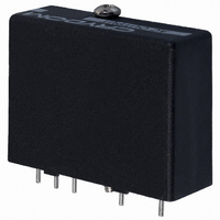
6412 Crydom Co., 6412 Datasheet - Page 2

6412
Manufacturer Part Number
6412
Description
I/O MODULE 24-280V SIP AC OUTPT
Manufacturer
Crydom Co.
Series
6r
Type
ACr
Datasheet
1.6421.pdf
(2 pages)
Specifications of 6412
Color
Black
Style
Standard
Voltage - Input
5VDC (3.5 ~ 6VDC)
Current - Input
20mA
Voltage - Output
24 ~ 280VAC (240VAC Nom)
Current - Output
0.02 ~ 3.5A
Turn On Time
1/2 Cycle
Turn Off Time
1/2 Cycle
Features
Hold Down Screw
Leaded Process Compatible
No
No. Of Analog Outputs
1
No. Of Digital Inputs
1
Output Voltage Min
24V
Supply Voltage Min
0VDC
Output Current Max
3.5A
Signal Input Type
3.5 To 6VDC
Output Type
AC
Output Voltage
280V
No. Of Outputs
1
Output Current
3.5A
Output Current Min
0.02A
Rohs Compliant
Yes
Lead Free Status / RoHS Status
Lead free / RoHS Compliant
Lead Free Status / RoHS Status
Lead free / RoHS Compliant, Lead free / RoHS Compliant
Other names
CC1242
Available stocks
Company
Part Number
Manufacturer
Quantity
Price
Company:
Part Number:
6412
Manufacturer:
TT ELECTRONICS/BI
Quantity:
5 510
Company:
Part Number:
641203-4
Manufacturer:
KET
Quantity:
53 250
Company:
Part Number:
641207-5
Manufacturer:
TE
Quantity:
53 251
Company:
Part Number:
641207-5
Manufacturer:
TE
Quantity:
35 000
BUFFERED OUTPUT MODULES
A buffered non-inverting module turns on when pin 4 is held in the
low state (logic 0), the same as standard modules driven in the sink
mode. A buffered inverting module conversely turns on when pin 4
is held high (logic 1). In the absence of an input signal and/or logic
supply (open Circuit), all models will be in the off-state.
Buffered modules may be used with standard 5 pin PB or MS
mounting boards. However, the 3.3K pull-up resistor will add to the
logic drive current of a non-inverting module and may be removed.
For an inverting module, the resistor must be removed to avoid a
false “on” command, unless a “normally closed” condition is desir-
able for use with a ground seeking (logic 0) signal source.
3.0
2.5
2.0
1.5
1.0
3.5
0
FastFax Document No. 308
081398, PAGE 2 OF 2
C U R R E N T D E R AT I N G C U RV E
Max. Load Current vs. Temp.
AMBIENT TEMPERATURE (ºC)
20
40
60
80
AC Output Buffered Modules
For recommended applications and more information contact:
USA: (800) 8 CRYDOM • (800) 827-9366 • (619) 715-7200 • fax (619) 715-7280
Crydom Corp, 9525 Chesapeake Drive, San Diego, CA 92123 • e-mail: sales@crydom.com
WEB SITE: http://www.crydom.com FASTFAX Product Information: (888) 267-9191
UK: (44)1202 812300 • fax (44)1202 812340 Crydom International Ltd., 85, Condor Close,
Woolsbridge Industrial Estate, Three-Legged Cross. Wimborne, Dorset, England BH21 6SU
GERMANY: (49) (0)6874 182580 • fax (49)(0)6874 182585 Crydom GmbH,
Gewerbegebiet Im Schachen, D-66687 Nunkirchen, Germany • e-mail: vertrieb@crydom.com
GENERAL SPECIFICATIONS
Min. Dielectric Input/Output (1 Minute)
Min. Isolation Resistance Input/Output (@ 500V)
Capacitance input to output
Temperature Range — Operating
Temperature Range — Storage
DC LOGIC
SUPPLY
DC LOGIC INPUT
STATUS
COM (-)
#4-40. PHILLIPS
LED
DOWN SCREW
.040 (1.0) DIA.
HEAD HOLD
(5 PLACES)
CAPTIVE
©1998 CRYDOM CORP Specifications subject to change without notice.
(+)
(31.7)
W I R I N G & M E C H A N I C A L D I A G R A M S
1.25
(6.3)
.25
3
4
5
All dimensions are in inches (millimeters)
INV or
NON-INV
LOGIC
5
4
3
BOTTOM VIEW
(40.6)
1.60
(35.5)
1.40
(43.1)
1.70
2
(30.5)
1.20
Zero
Switch
(25.4)
1.00
(17.8)
1
.70
(7.6)
.30
-40˚ C to 125˚ C
-40˚ C to 80˚ C
4,000 VRMS
10
(2.5)
.100
(7.6)
.30
10
8 pF
Ohms
(15.2)
AC
OUTPUT
1
2
.60
LOAD
~
9002


