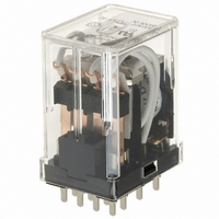
HC4-HP-DC24V Panasonic Electric Works, HC4-HP-DC24V Datasheet - Page 6

HC4-HP-DC24V
Manufacturer Part Number
HC4-HP-DC24V
Description
RELAY PWR 5A 4PDT 24VDC PCB
Manufacturer
Panasonic Electric Works
Series
HCr
Type
Miniature Relayr
Specifications of HC4-HP-DC24V
Relay Type
General Purpose
Contact Form
4PDT (4 Form C)
Contact Rating (current)
5A
Switching Voltage
250VAC
Coil Type
Standard
Coil Current
37mA
Coil Voltage
24VDC
Turn On Voltage (max)
19.2 VDC
Turn Off Voltage (min)
2.4 VDC
Mounting Type
Through Hole
Termination Style
PC Pin
Circuit
4PDT (4 Form C)
Contact Rating @ Voltage
5A @ 250VAC
Control On Voltage (max)
19.2 VDC
Control Off Voltage (min)
2.4 VDC
Brand/series
HC Series
Current, Rating
5 A
Function
General Purpose
Power, Rating
1250 VA
Standards
UL, CSA, VDE
Termination
Solder
Voltage, Control
24 VDC
Voltage, Rating
250 VAC
Relay Construction
Non-Latching
Contact Arrangement
4PDT
Coil Voltage Dc
24V
Voltage Rating (vac)
250V
Dropout Volt (min)
2.4VDCV
Coil Resistance
650Ohm
Pick-up Voltage (max)
19.2VDC
Maximum Power Rating
1.25KVA
Operate Time
20ms
Contact Current Rating
5A
Contact Material
AgNi/Au Clad
Coil Suppression Diode
No
Push To Test Button
No
Led Indicator
No
Seal
Unsealed
Product Height (mm)
36.7mm
Product Depth (mm)
20.8mm
Product Length (mm)
27.2mm
Operating Temp Range
-50C to 70C
Pin Count
14
Mounting Style
Through Hole
Package / Case
Dust Cover
Lead Free Status / RoHS Status
Lead free / RoHS Compliant
Other names
255-1921
HC4-HP-DC24V
HC4-HP-DC24V
Available stocks
Company
Part Number
Manufacturer
Quantity
Price
Company:
Part Number:
HC4-HP-DC24V
Manufacturer:
PANASONIC
Quantity:
5 400
Latching relay types: HC2K
TYPES AND COIL DATA
DC coils at 20 C
AC coils
HC2K AC types are not recognized by UL, CSA.
Notes: 1. The coil current range is 10% of the nominal coil current.
SPECIFICATIONS
Contacts
Coil
#1 This value can change due to the switching frequency, environmental conditions,
DIMENSIONS AND CIRCUIT DIAGRAM
.138
.020
0.5
HC2K-DC6V (-F)
HC2K-DC12V (-F)
HC2K-DC24V (-F)
HC2K-DC48V (-F)
HC2K-DC100V (-F)
HC2K-AC6V (-F)
HC2K-AC12V (-F)
HC2K-AC24V (-F)
HC2K-AC48V (-F)
HC2K-AC115V (-F)
Arrangement
Initial contact resistance max.
(By voltage drop 6 V DC 1 A)
Rating
(resistive)
Nominal operating power
3.5
and desired reliability level, therefore it is recommended to check this with the
actual load.
.197
5.0
mm
Dimensions
2. The relay is suitable to the range of 80% — 110% of the nominal coil voltage. However, it is recommended that the relay be used in the range
3. UL/CSA approved type is standard.
1
.039
inch
Plug-in
Plug-in
of 85% — 110% of the nominal coil voltage, with the temporary voltage variation taken into consideration.
1.319
.827
33.5
21
Nominal switching capacity
Max. switching power
Max. switching current
Min. switching capacity
Part No.
Part No.
68 F
1.079
27.4
HC2K-P-DC6V (-F)
HC2K-P-DC12V (-F)
HC2K-P-DC24V (-F)
HC2K-P-DC48V (-F)
HC2K-P-DC100V (-F)
HC2K-P-AC6V (-F)
HC2K-P-AC12V (-F)
HC2K-P-AC24V (-F)
HC2K-P-AC48V (-F)
HC2K-P-AC115V (-F)
PC board terminal
PC board terminal
27.4
1.074
.059
1.5
Plug-in
General tolerance: 0.5
33.5
1.319
Set coil
Reset coil
13.35
.526
.827
21
#1
Circuit diagram
4.45
.175
4.51
.178
4.06
.160
6.35
.250
6.35
.250
Nominal coil current
Nominal coil current
0.51 VA to 0.88 VA
1.2 VA to 1.33 VA
51.1
25.3
15.6
25.2
10.4
207
100
206
100
set
set
51
HC magnetic latching relays are particularly suitable for various vending machines,
remote control devices, parking meters, conveyor, NC machinery, etc.
2 Form C only
3 A 250 V AC
1 mA, 1 V DC
750 VA
50 m
(mA)
(mA)
.020
3A
reset
reset
52.2
25.5
13.7
21.4
18.5
107
103
5.8
5.4
52
PC board pattern (Copper-side)
4.45
.175
Tolerance: 0.1
Nominal operating
Nominal operating
1.24
1.20
1.23
1.21
1.56
1.23
1.20
1.22
1.20
1.2
set
set
13.35
.827
8.9
.526
21
power (VA)
power (VA)
Characteristics
.350
Initial breakdown
voltage
Set time (at nominal voltage) (at 20°C)
Reset time (at nominal voltage)
Temperature rise
(at nominal voltage)
Shock/vibration resistance
Expected life
(min. operations)
Ambient temperature
10-2 DIA. HOLES
10-.079 DIA. HOLES
Idle terminal hole needed
0.621
reset
reset
0.64
0.63
0.61
0.66
0.58
0.62
0.62
0.51
0.88
27.4
1.079
.004
mm
inch
Nominal
Nominal
Pick-up
Pick-up
voltage
voltage
80% of
80% of
Between contact
and coil
Mechanical
(at 180 cpm)
Electrical (resistive)
(at 20 cpm)
UL, CSA recognized
Coil voltage
Coil voltage
Notes:
1. Configuration and dimensions of HC2K
types are the same as those of standard HC4
types. Standard sockets and screw terminal
sockets of HC4 can be used: HC4-SS-K,
HC4-PS-K, HC4-WS-K, and HC4-HSF-K.
2. Please note that circuit diagram of HC2K is
different from HC4.
3. Avoid operation by capacitor since latching
force varies according to input pulse voltage.
Set coil
Reset coil
Max. allowable
Max. allowable
110% of
Nominal
110% of
Nominal
voltage
voltage
(Not freezing and condens-
AC, DC: Approx. 20 ms
ing at low temperature)
1,500 Vrms for 1 min.
Min. 98 m/s
DC: Approx. 50 ms
AC: Approx. 30 ms
–40 F to +122 F
–40 C to +50 C
Max. 80 C
Max. 50 C
PC board terminal
2 10
10
Plug-in
7
2
5
{10 G}
HC


