JTN1AS-PA-F-DC12V Panasonic Electric Works, JTN1AS-PA-F-DC12V Datasheet
JTN1AS-PA-F-DC12V
Manufacturer Part Number
JTN1AS-PA-F-DC12V
Description
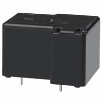
RELAY POWER 30A 12VDC PCB
Manufacturer
Panasonic Electric Works
Series
JT-Nr
Type
Power Relayr
Specifications of JTN1AS-PA-F-DC12V
Relay Type
General Purpose
Contact Form
SPST-NO (1 Form A)
Contact Rating (current)
30A
Switching Voltage
277VAC
Coil Type
Standard
Coil Current
66.7mA
Coil Voltage
12VDC
Turn On Voltage (max)
9 VDC
Turn Off Voltage (min)
1.2 VDC
Mounting Type
Through Hole
Termination Style
PC Pin
Circuit
SPST-NO (1 Form A)
Contact Rating @ Voltage
30A @ 277VAC
Control On Voltage (max)
9 VDC
Control Off Voltage (min)
1.2 VDC
Brand/series
JT-N Series
Current, Rating
30 A
Dimensions
1.256 in. L x 1.059 in. W x 0.795 in. D
Function
Automotive
Material, Contact
Silver Alloy
Number Of Pins
4
Power, Rating
8310 VA
Standards
UL, CSA
Temperature, Operating, Maximum
+85 °C (Ambient)
Temperature, Operating, Minimum
-55 °C (Ambient)
Termination
Solder
Voltage, Control
12 VDC
Voltage, Rating
277 VAC
Relay Construction
Non-Latching
Contact Arrangement
SPST-NO
Coil Voltage Dc
12V
Voltage Rating (vac)
277V
Dropout Volt (min)
1.2VDCV
Coil Resistance
180Ohm
Pick-up Voltage (max)
9VDC
Maximum Power Rating
8.31KVA
Operate Time
20ms
Contact Current Rating
30A
Contact Material
Ag
Coil Suppression Diode
No
Push To Test Button
No
Led Indicator
No
Seal
Sealed
Product Height (mm)
20.2mm
Product Depth (mm)
26.9mm
Product Length (mm)
31.9mm
Operating Temp Range
-55C to 85C
Pin Count
4
Mounting Style
Through Hole
Lead Free Status / RoHS Status
Lead free / RoHS Compliant
Other names
255-1719


SPECIFICATIONS
Contacts
* The life is for open venting-hole condition.
Coil at 20°C
TYPICAL APPLICATIONS
• Automotive
• Air conditioner
• Heating & ventilation
• Home appliance
Arrangement
Initial contact resistance, max.
(By voltage drop method,
6 V DC 1 A)
Contact material
Rating
Expected
life
Nominal operating power
Max. switching power
Max. switching voltage
Max. switching current
Min. switching
capacity
Mechanical
Electrical
(Resistive load)
68°F
PCB type
#1
20 A 277 V AC
Min. 1 10
1 Form A
8310 VA
30 A
COMPACT ECONOMICAL
PCB & TMP type
Approx. 800 mW
100 mA, 5 V DC
Silver alloy
TMP type
Min. 1 10
277 V AC
5
*
50 m
30 AMP. RELAY
20 A 277 V AC
10 A 277 V AC
N.O.: 5540 VA
N.C.: 2770 VA
Min. 1 10
Min. 1 10
N.O.: 20 A
N.C.: 10 A
1 Form C
7
N.O.:
N.C.:
5
5
*
*
FEATURES
• High switching capacity — 30 A for 1 Form A
• 2 contact arrangements — 1 Form A or 1 Form C
• “TMP” types available
• UL/CSA recognized
• Class F types standard
Characteristics
#1 This value can change due to the switching frequency, environmental conditions,
Remarks
* Speci cations will v ary with foreign standards certi cation r atings.
*
*
*
*
*
*
*
Initial insulation resistance*
Initial
breakdown
voltage*
Operate time*
(at nominal voltage)
Release time (without diode)*
(at nominal voltage)
Shock
resistance
Vibration
resistance
Conditions for
operation, trans-
port and storage*
(Not freezing and
condensing at low
temperature)
Unit weight
1
2
3
4
5
6
7
Measurement at same location as “Initial breakdown voltage” section
Detection current: 10 mA
Excluding contact bounce time
Half-wave pulse of sine wave: 11ms; detection time: 10 s
Half-wave pulse of sine wave: 6ms
Detection time: 10 s
Refer to 6. Conditions for operation, transport and storage mentioned in
AMBIENT ENVIRONMENT
and desired reliability level, therefore it is recommended to check this with the
actual load.
2
Between contacts
Between contacts
and coil
3
7
Functional*
Destructive*
Functional*
Destructive
Ambient
temp.
Humidity
1
RELAYS
3
4
6
5
Max. 117.6 m/s
Max. 88.2 m/s
–55°C to +85°C
JT-N
at double amplitude of 1.5 mm
at double amplitude of 2 mm
Min. 100 M
Approx. 30 g
Min. 980 m/s
Approx. 25 g
Min. 98 m/s
PCB & TMP type
5 to 85% R.H.
Max. 20 ms
Max. 10 ms
1,200 Vrms
2,500 Vrms
TMP type:
PCB type:
2
2
{12 G}, 10 to 55 Hz
{9 G}, 10 to 55 Hz
–67°F to +185°F
at 500 V DC
2
2
(1.06 oz)
(.88 oz)
{10 G}
{100 G}
JT-N
Related parts for JTN1AS-PA-F-DC12V
Image
Part Number
Description
Manufacturer
Datasheet
Request
R

Part Number:
Description:
RELAY POWER 30A 5VDC SEALED PCB
Manufacturer:
Panasonic Electric Works
Datasheet:
Part Number:
Description:
RELAY POWER 30A 24VDC PCB
Manufacturer:
Panasonic Electric Works
Datasheet:
Part Number:
Description:
RELAY POWER 30A 15VDC SEALED PCB
Manufacturer:
Panasonic Electric Works
Datasheet:
Part Number:
Description:
RELAY POWER 30A 6VDC SEALED PCB
Manufacturer:
Panasonic Electric Works
Datasheet:
Part Number:
Description:
RELAY POWER 30A 9VDC SEALED PCB
Manufacturer:
Panasonic Electric Works
Datasheet:
Part Number:
Description:
RELAY POWER 30A 18VDC SEALED PCB
Manufacturer:
Panasonic Electric Works
Datasheet:
Part Number:
Description:
RELAY POWER 30A 48VDC SEALED PCB
Manufacturer:
Panasonic Electric Works
Datasheet:

Part Number:
Description:
RELAY POWER 30A 15VDC SEALED TMP
Manufacturer:
Panasonic Electric Works
Datasheet:
Part Number:
Description:
RELAY POWER 30A 18VDC SEALED TMP
Manufacturer:
Panasonic Electric Works
Datasheet:
Part Number:
Description:
RELAY POWER 30A 5VDC TMP
Manufacturer:
Panasonic Electric Works
Datasheet:

Part Number:
Description:
CONN SOCKET P4 .4MM 50POS SMD
Manufacturer:
Panasonic Electric Works
Datasheet:

Part Number:
Description:
CONN SOCKET .8MM 16POS SMD
Manufacturer:
Panasonic Electric Works
Datasheet:
Part Number:
Description:
CONN HEADER .8MM 16POS SMD
Manufacturer:
Panasonic Electric Works
Datasheet:
Part Number:
Description:
CONN SOCKET .8MM 20POS SMD
Manufacturer:
Panasonic Electric Works
Datasheet:
Part Number:
Description:
CONN SOCKET .8MM 20POS SMD
Manufacturer:
Panasonic Electric Works
Datasheet:
JTN1AS-PA-F-DC12V Summary of contents
Page 1
... Half-wave pulse of sine wave: 11ms; detection time Half-wave pulse of sine wave: 6ms 5 * Detection time Refer to 6. Conditions for operation, transport and storage mentioned in 7 AMBIENT ENVIRONMENT JT-N RELAYS PCB & TMP type Min. 100 M 1 Between contacts 1,200 Vrms Between contacts 2,500 Vrms 2 and coil 3 Max Max ...
Page 2
... JT-N ORDERING INFORMATION JT-N Relays (PCB and TMP type) Contact arrangement 1a: 1 Form Form C Notes: 1. UL/CSA approved type is standard. 2. Standard packing: PCB type: Carton: 50 pcs. Case: 500 pcs. COIL DATA (at 20°C 68°F) Nominal Pick-up voltage, Drop-out voltage, voltage (max.) (Initial (min ...