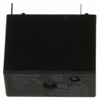
G5Q-14 DC5 Omron, G5Q-14 DC5 Datasheet - Page 2
G5Q-14 DC5
Manufacturer Part Number
G5Q-14 DC5
Description
RELAY PWR SPDT 5VDC PCB
Manufacturer
Omron
Series
G5Qr
Specifications of G5Q-14 DC5
Relay Type
General Purpose
Coil Type
Standard
Contact Form
SPDT (1 Form C)
Contact Rating (current)
10A
Switching Voltage
277VAC, 30VDC - Max
Coil Current
80mA
Coil Voltage
5VDC
Turn On Voltage (max)
3.75 VDC
Turn Off Voltage (min)
0.25 VDC
Mounting Type
Through Hole
Termination Style
PC Pin
Circuit
SPDT (1 Form C)
Contact Rating @ Voltage
10A @ 125VAC
Control On Voltage (max)
3.75 VDC
Control Off Voltage (min)
0.25 VDC
Coil Voltage Vdc Nom
5V
Contact Current Max
10A
Contact Voltage Ac Nom
250V
Contact Voltage Dc Nom
30V
Coil Resistance
63ohm
Contact Configuration
SPDT
Current, Rating
10 A (NO), 3 A (NC)
Function
General Purpose
Number Of Pins
5
Power, Rating
1250 VA⁄150 W (NO), 375 VA⁄90 W (NC)
Standards
UL, CSA, RoHS, VDE
Termination
Through Hole
Voltage, Control
5 VDC
Voltage, Rating
125 VAC
Lead Free Status / RoHS Status
Lead free / RoHS Compliant
Lead Free Status / RoHS Status
Lead free / RoHS Compliant, Lead free / RoHS Compliant
Other names
G5Q-14DC5
G5Q-14DC5
G5Q14DC5
Z2929
G5Q-14DC5
G5Q14DC5
Z2929


G5Q
Specifications
Note:
Note:
2
SPST-NO
SPDT
Item
Contact mechanism
Contact material
Rated load
Rated carry current
Max. switching voltage
Max. switching current
Item
Contact resistance (See note 2.)
Operate time
Release time
Insulation resistance (See note 3.)
Dielectric strength
Impulse withstand voltage (between coil and contacts)
Vibration resistance
Shock resistance
Endurance
Failure rate (reference value) (See note 4.)
Ambient operating temperature range
Ambient operating humidity range
Weight
Coil Ratings
Contact Ratings
Characteristics
Contact
form
1. The rated voltage and coil resistance are given at a coil temperature of 23 C and with a tolerance of 10%.
2. The operating characteristics are given at a coil temperature of 23 C.
3. The maximum voltage is the maximum voltage that can be applied to the relay coil.
1. The data shown above are initial values.
2. The contact resistance is measured with 1 A applied at 5 VDC using a fall-of-potential method.
3. The insulation resistance is measured at the same points as the dielectric strength using a 500-VDC ohmmeter.
4. P level:
Rated voltage (V)
VDC
60
Load
= 0.1
Between coil and contacts
Between contacts of same polarity
Destruction
Malfunction
Destruction
Malfunction
Mechanical
Electrical
Single
Ag alloy (Cd free)
10 A at 125 VAC
3 A at 250 VAC
5 A at 30 VDC
10 A (NO)/3 A (NC)
277 VAC, 30 VDC
AC: 10 A (NO)/3 A (NC)
DC: 5 A (NO)/3 A (NC)
5
9
12
24
5
9
12
24
10
6
SPST-NO
/operation
Item
Resistive load
40
22.2
16.7
8.3
80
44.4
33.3
16.7
current (mA)
Rated
10 A at 125 VAC (NO)
3 A at 250 VAC (NO)
5 A at 30 VDC (NO)
3 A at 125 VAC (NC)
3 A at 30 VDC (NC)
Type
125
405
720
2880
63
202
360
1440
SPDT
resistance
100 m
10 ms max.
5 ms max.
1,000 m
4,000 VAC, 50/60 Hz for 1 min
1,000 VAC, 50/60 Hz for 1 min
8 kV (1.2
10 to 55 to 10 Hz, 0.75-mm single amplitude (1.5-mm double amplitude)
10 to 55 to 10 Hz, 0.75-mm single amplitude (1.5-mm double amplitude)
1000 m/s
100 m/s
10,000,000 operations (18,000 operations per hour)
200,000 operations: 3 A (NO)/3 A (NC) at 125 VAC, resistive load
100,000 operations: 3 A (NO)/3 A (NC) at 250 VAC,
50,000 operations:
10 mA at 5 VDC
5% to 85%
Approx. 6.5 g
40 C to 85 C (with no icing or condensation)
Coil
( )
2
max.
2
min.
50 s)
75% max. of
rated voltage
Must-operate
voltage (V)
5 A (NO)/3 A (NC) at 30 VDC, resistive load
10 A at 125 VAC (900 operations per hour)
Standard models
5% min. of
rated voltage
Must-release
voltage (V)
190% of rated
voltage
(at 23 C)
Max. voltage
(V)
Approx. 200
Approx. 400
consumption
Power
(mW)
G5Q
Related parts for G5Q-14 DC5
Image
Part Number
Description
Manufacturer
Datasheet
Request
R

Part Number:
Description:
RELAY PC MNT PWR SPDT 10A 12VDC
Manufacturer:
Omron
Datasheet:
Part Number:
Description:
RELAY PC MNT PWR SPDT 10A 24VDC
Manufacturer:
Omron
Datasheet:

Part Number:
Description:
RELAY PWR SPDT 18VDC PCB
Manufacturer:
Omron
Datasheet:
Part Number:
Description:
Power PCB Relay
Manufacturer:
Omron
Datasheet:
Part Number:
Description:
Power PCB Relay
Manufacturer:
Omron
Datasheet:
Part Number:
Description:
Power PCB Relay
Manufacturer:
Omron
Datasheet:
Part Number:
Description:
Power PCB Relay
Manufacturer:
Omron
Datasheet:
Part Number:
Description:
POWER PCB RELAY
Manufacturer:
Omron
Datasheet:
Part Number:
Description:
Power PCB Relay
Manufacturer:
Omron
Datasheet:
Part Number:
Description:
Power PCB Relay
Manufacturer:
Omron
Datasheet:
Part Number:
Description:
Power PCB Relay
Manufacturer:
Omron
Datasheet:

Part Number:
Description:
RELAY, PCB, SPCO, 12VDC
Manufacturer:
Omron
Datasheet:
Part Number:
Description:
RELAY, PCB, SPCO, 24VDC
Manufacturer:
Omron
Datasheet:
Part Number:
Description:
RELAY, PCB, SPCO, 5VDC, SEALED
Manufacturer:
Omron
Datasheet: