G6K-2P DC4.5 Omron, G6K-2P DC4.5 Datasheet - Page 5
G6K-2P DC4.5
Manufacturer Part Number
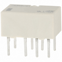
G6K-2P DC4.5
Description
RELAY TELCOM DPDT 1A 4.5VDC PCB
Manufacturer
Omron
Series
G6Kr
Specifications of G6K-2P DC4.5
Coil Type
Standard
Coil Current
23.2mA
Relay Type
Telecom
Circuit
DPDT (2 Form C)
Contact Rating @ Voltage
1A @ 30VDC
Coil Voltage
4.5VDC
Control On Voltage (max)
3.6 VDC
Control Off Voltage (min)
0.45 VDC
Mounting Type
Through Hole
Termination Style
PC Pin
Contact Configuration
DPDT
Contact Current Max
1A
Contact Voltage Ac Nom
125V
Contact Voltage Dc Nom
30V
Coil Voltage Vdc Nom
4.5V
Contact Form
DPDT
Current, Rating
0.3⁄1 AAC⁄ADC
Function
Sensitive
Number Of Pins
8
Power, Rating
37.5⁄30 VA⁄W
Standards
UL, CSA, RoHS
Termination
Through Hole
Voltage, Control
4.5 VDC
Voltage, Rating
125 VAC
Lead Free Status / RoHS Status
Lead free / RoHS Compliant
Lead Free Status / RoHS Status
Lead free / RoHS Compliant, Lead free / RoHS Compliant
Other names
G6K-2P-DC4.5
G6K2PDC4.5
G6K2PDC45
Z115
G6K2PDC4.5
G6K2PDC45
Z115


G6K
Note:
Note 1: The test was conducted at an ambient temperature of 23°C.
High-frequency Characteristics
(Isolation)
G6K-2G (F/P), G6K-2G (F/P)-Y
Contact Reliability Test
G6K-2G (F/P), G6K-2G (F/P)-Y
100
10
20
30
40
50
60
70
80
90
0
1
External Magnetic Interference
G6K-2G (F/P), G6K-2G (F/P)-Y
Operating frequency (x10 operations)
Number of Relays: 10
Sample: G6K-2G
2: The contact resistance data are periodically measured reference values and are not values from each monitoring operation.
Sample: G6K-2G
Number of Relays: 10
Test conditions: 10 mA resistive load at
10 mVDC with an operation rate of 50 %
Switching frequency: 7,200 operations/h
1. The tests were conducted at an ambient temperature of 23 ° C.
2. High-frequency characteristics depend on the PCB to which the Relay is mounted. Always check these characteristics including
Sample: G6K-2G
Number of Relays: 10
endurance in the actual machine before use.
Contact resistance values will vary according to the switching frequency and operating environment, so be sure to check
operation under the actual operating conditions before use.
External magnetic field (A/m)
10
Frequency (MHz)
(Average value)
(Average value)
Must operate voltage
Must release voltage
3
(See note.)
NO
contact
NC
contact
100
Not energized
0.1
0.2
0.3
0.4
0.5
High-frequency Characteristics
(Insertion Loss)
G6K-2G (F/P), G6K-2G (F/P)-Y
0
Energized
1
Sample: G6K-2G
Number of Relays: 10
Sample
Sample
Mutual Magnetic Interference
G6K-2G (F/P), G6K-2G (F/P)-Y
Sample: G6K-2G
Number of Relays: 10
External magnetic field (A/m)
10
Frequency (MHz)
(Average value)
Initial stage
Initial stage
(Average value)
Must operate voltage
Must release voltage
Must operate voltage
Must release voltage
Average value
Average value
100
Test
Test
10
20
30
40
50
60
70
80
0
High-frequency Characteristics
(Return Loss)
G6K-2G (F/P),G6K-2G (F/P)-Y
Mutual Magnetic Interference
G6K-2G (F/P), G6K-2G (F/P)-Y
1
Sample
Return loss
Sample: G6K-2G
Number of Relays: 10
Sample
V.SWR
Sample: G6K-2G
Number of Relays: 10
Not energized
Energized
External magnetic field (A/m)
10
Must operate voltage
Must release voltage
Initial stage
Frequency (MHz)
Initial stage
(Average value)
(Average value)
Average value
Average value
Must operate voltage
Must release voltage
G6K
Test
Test
100
1.4
1.35
1.3
1.25
1.2
1.15
1.1
1.05
1
5
Related parts for G6K-2P DC4.5
Image
Part Number
Description
Manufacturer
Datasheet
Request
R

Part Number:
Description:
LOW SIGNAL RELAY
Manufacturer:
Omron
Datasheet:
Part Number:
Description:
LOW SIGNAL RELAY
Manufacturer:
Omron
Datasheet:

Part Number:
Description:
RELAY TELCOM DPDT 1A 12VDC PCB
Manufacturer:
Omron
Datasheet:
Part Number:
Description:
RELAY PC MNT DPDT 1A 5V
Manufacturer:
Omron
Datasheet:
Part Number:
Description:
RELAY TELCOM DPDT 1A 5VDC PCB
Manufacturer:
Omron
Datasheet:
Part Number:
Description:
RELAY PC MNT DPDT 1A 4.5V
Manufacturer:
Omron
Datasheet:
Part Number:
Description:
RELAY PC MNT DPDT 1A 12V
Manufacturer:
Omron
Datasheet:
Part Number:
Description:
RELAY PC MNT DPDT 1A 24V
Manufacturer:
Omron
Datasheet:

Part Number:
Description:
LOW SIGNAL RELAY
Manufacturer:
Omron
Datasheet:
Part Number:
Description:
LOW SIGNAL RELAY
Manufacturer:
Omron
Datasheet:
Part Number:
Description:
LOW SIGNAL RELAY
Manufacturer:
Omron
Datasheet:

Part Number:
Description:
LOW SIGNAL RELAY
Manufacturer:
Omron
Datasheet:
Part Number:
Description:
LOW SIGNAL RELAY
Manufacturer:
Omron
Datasheet:

Part Number:
Description:
RELAY, PCB, DPCO, 12VDC
Manufacturer:
Omron
Datasheet:
Part Number:
Description:
RELAY, PCB, DPCO, 5VDC
Manufacturer:
Omron
Datasheet: