G6K-2F-RF DC5 Omron, G6K-2F-RF DC5 Datasheet - Page 2
G6K-2F-RF DC5
Manufacturer Part Number
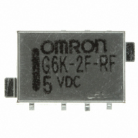
G6K-2F-RF DC5
Description
RELAY HI FREQ RF DPDT 5V SMT
Manufacturer
Omron
Series
G6K-RFr
Datasheet
1.G6K-2F-RF-S_DC5.pdf
(8 pages)
Specifications of G6K-2F-RF DC5
Relay Type
RF
Circuit
DPDT (2 Form C)
Contact Rating @ Voltage
1A @ 30VDC
Coil Type
Standard
Coil Current
21.1mA
Coil Voltage
5VDC
Control On Voltage (max)
4 VDC
Control Off Voltage (min)
0.5 VDC
Mounting Type
Surface Mount
Termination Style
Gull Wing
Contact Form
DPDT
Current, Rating
0.3⁄1 AAC⁄ADC
Function
Frequency (RF)
Number Of Pins
8
Power, Rating
37.5⁄30 VA⁄W
Standards
RoHS
Termination
Surface Mount
Voltage, Control
5 VDC
Voltage, Rating
125 VAC
Lead Free Status / RoHS Status
Lead free / RoHS Compliant
Other names
G6K-2F-RF-DC5
G6K2FRFDC5
Z2037
G6K2FRFDC5
Z2037


■ Coil Ratings
Note: 1. The rated current and coil resistance are measured at a coil temperature of 23°C with a tolerance of ±10%.
■ High Frequency Characteristics at 1 GHz
Note: 1. The impedance of the measurement system is 50 Ω.
■ Characteristics
Note: 1. The above values are initial values.
322
Rated voltage
3 VDC
4.5 VDC
5 VDC
6 VDC
9 VDC
12 VDC
24 VDC
Isolation
Insertion loss
V.S.W.R.
Maximum transmission capacity
Maximum switching capacity
Contact resistance (See note 2.)
Operating (set) time (See note 3.)
Release (reset) time (See note 3.)
Minimum set/reset pulse time
Insulation resistance (See note 4.)
Dielectric strength
Vibration resistance
Shock resistance
Endurance
Ambient temperature
Ambient humidity
Weight
2. The operating characteristics are measured at a coil temperature of 23°C.
3. The maximum voltage is the highest voltage that can be imposed on the Relay coil instantaneously.
2. The above values are initial
3. These values are for a load with V.S.W.R.
2. The contact resistance was measured with 10 mA at 1 VDC with a voltage drop method.
3. Values in parentheses are typical values.
4. The insulation resistance was measured with a 500-VDC megohmmeter applied to the same parts as those used for checking the dielectric strength.
High Frequency Relay
Rated current
33.0 mA
23.2 mA
21.1 mA
17.6 mA
11.3 mA
9.1 mA
4.6 mA
Item
Between coil and
contacts
Between contacts of
different poles
Between contacts of the
same pole
Between ground and
coil/contacts
Destruction
Malfunction
Malfunction
Mechanical
Electrical
Destruction
20 dB min. between contacts of the same pole
30 dB min. between contacts of different poles
0.2 dB max.
1.2 max.
3 W (See note 3)
1 W (See note 3)
Coil resistance
91 Ω
194 Ω
237 Ω
341 Ω
795 Ω
1,315 Ω
5,220 Ω
G6K-RF
≤
1.2
100 mΩ max.
3 ms max. (approx. 1.4 ms)
3 ms max. (approx. 1.3 ms)
---
1,000 MΩ min. (at 500 VDC)
750 VAC, 50/60 Hz for 1 min
750 VAC, 50/60 Hz for 1 min
750 VAC, 50/60 Hz for 1 min
500 VAC, 50/60 Hz for 1 min
10 to 55 Hz, 5-mm double amplitude and 55 to 500 to 55 Hz, 300 m/s
10 to 55 Hz, 3.3-mm double amplitude and 55 to 500 to 55 Hz, 200 m/s
1,000 m/s
750 m/s
50,000,000 operations min. (at a switching frequency of 36,000 operations/hour)
100,000 operations min. (at a switching frequency of 1,800 operations/hour)
Operating: −40°C to 70°C (with no icing or condensation)
Operating: 5% to 85%
Approx. 0.95 g
Must operate
voltage
80% max. of rated
voltage
(75% max. of rated
set voltage for
latching models)
Single-side stable models
2
2
G6K-2F-RF(-S)
Must release
voltage
10% min. of rated
voltage
(75% max. of rated
reset voltage for
latching models)
Maximum voltage
150% of rated voltage Approx. 100 mW
3 ms max. (approx. 1.2 ms)
3 ms max. (approx. 1.2 ms)
10 ms
Single-winding latching models
G6KU-2F-RF(-S)
Rated power
consumption
2
2
Related parts for G6K-2F-RF DC5
Image
Part Number
Description
Manufacturer
Datasheet
Request
R

Part Number:
Description:
RELAY SMT DPDT 1A 5VDC T/R
Manufacturer:
Omron
Datasheet:

Part Number:
Description:
RELAY SMT DPDT 1A 5VDC T/R
Manufacturer:
Omron
Datasheet:
Part Number:
Description:
RELAY SMT DPDT 1A 12VDC T/R
Manufacturer:
Omron
Datasheet:
Part Number:
Description:
RELAY SMT DPDT 1A 12VDC T/R
Manufacturer:
Omron
Datasheet:

Part Number:
Description:
SMT TAPE-N-REEL RELAY
Manufacturer:
Omron
Datasheet:
Part Number:
Description:
SMT TAPE-N-REEL RELAY
Manufacturer:
Omron
Datasheet:

Part Number:
Description:
High Frequency Relay
Manufacturer:
Omron
Datasheet:
Part Number:
Description:
SMT TAPE-N-REEL RELAY
Manufacturer:
Omron
Datasheet:
Part Number:
Description:
SMT TAPE-N-REEL RELAY
Manufacturer:
Omron
Datasheet:
Part Number:
Description:
SMT TAPE-N-REEL RELAY
Manufacturer:
Omron
Datasheet:
Part Number:
Description:
SMT RELAY
Manufacturer:
Omron
Datasheet:
Part Number:
Description:
SMT RELAY
Manufacturer:
Omron
Datasheet:
Part Number:
Description:
SMT TAPE-N-REEL RELAY
Manufacturer:
Omron
Datasheet:
Part Number:
Description:
SMT TAPE-N-REEL RELAY
Manufacturer:
Omron
Datasheet:
Part Number:
Description:
SMT TAPE-N-REEL RELAY
Manufacturer:
Omron
Datasheet: