TQ2-4.5V Panasonic Electric Works, TQ2-4.5V Datasheet - Page 9
TQ2-4.5V
Manufacturer Part Number
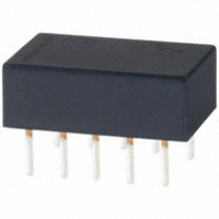
TQ2-4.5V
Description
RELAY STD DPDT 1A 4.5VDC PC MNT
Manufacturer
Panasonic Electric Works
Series
TQr
Type
General Purpose Relayr
Specifications of TQ2-4.5V
Relay Type
Telecom
Circuit
DPDT (2 Form C)
Contact Rating @ Voltage
1A @ 30VDC
Coil Type
Standard
Coil Current
31.1mA
Coil Voltage
4.5VDC
Control On Voltage (max)
3.38 VDC
Control Off Voltage (min)
0.45 VDC
Mounting Type
Through Hole
Termination Style
PC Pin
Brand/series
TQ Series
Contact Form
DPDT
Current, Rating
0.5⁄1 AAC⁄ADC
Diameter, Mounting
0.039 in. Dia. (Hole)
Dimensions
0.551 in. L x 0.354 in. W x 0.197in. + 0.016 in. - 0.008 in. H
Function
General Purpose
Latch Type
Single Side Stable
Material, Contact
Gold-Clad Silver
Number Of Pins
10
Standards
UL, CSA
Termination
Solder
Voltage, Control
4.5 VDC
Voltage, Rating
125 VAC
Surge Voltage Withstand
1500 V FCC Part 68
Relay Construction
Non-Latching
Contact Arrangement
DPDT
Coil Voltage Dc
4.5V
Voltage Rating (vdc)
110V
Voltage Rating (vac)
125V
Dropout Volt (min)
0.45VDCV
Coil Resistance
144.6Ohm
Pick-up Voltage (max)
3.38VDC
Maximum Power Rating
30W/62.5VA
Operate Time
3ms
Contact Current Rating
1A
Contact Material
Ag/Au Clad
Coil Suppression Diode
No
Push To Test Button
No
Led Indicator
No
Seal
Unsealed
Product Height (mm)
5mm
Product Depth (mm)
9mm
Product Length (mm)
14mm
Operating Temp Range
-40C to 70C
Pin Count
8
Mounting Style
Through Hole
Package / Case
DIP
Lead Free Status / RoHS Status
Lead free / RoHS Compliant
Other names
255-1226
255-1226-5
255-1226
255-1226-5
255-1226
Available stocks
Company
Part Number
Manufacturer
Quantity
Price
Company:

Part Number:
TQ2-4.5V
Manufacturer:
FUJITSU
Quantity:
12 000
Part Number:
TQ2-4.5V
Manufacturer:
NAIS
Quantity:
20 000


11. Actual load test (35 mA 48 V DC wire spring relay load)
Circuit
12. 0.1 A 53 V DC resistive load test
Change of pick-up and drop-out voltage
13. Distribution of M.B.B. time
Tested sample: TQ2-2M-5V, 85 pcs.
Surface-mount terminal
1. Maximum switching capacity
ds_61020_en_tq: 010611J
60
50
40
30
20
10
0
57 V
DC
100
90
80
70
60
50
40
30
20
10
19
15
10
50
3.0
2.0
1.0
0.5
0.4
0.3
0.2
0
0
100 150
AC resistive load
26
21
50
Wire spring relay Circuit diagram
500
20 30
100
30
19
Drop-out voltage
Pick-up voltage
220Ω
220Ω
No. of operations, ×10
Terminal Nos. 2-3-4: ON
Terminal Nos. 7-8-9: ON
150
200
17
11
1,000
Contact voltage, V
50
200
250
−
−
x:
3σ
Min.: 23 μs
Max.: 243 μs
x:
3σ
Min.: 35 μs
Max.: 254 μs
6
4
n-1
n-1
DC resistive load
100
: 163.8 μs
: 167.3 μs
250
300
1,500
105.6 μs
115.6 μs
2
300 μs min.
350 μs max.
200 300
20Hz
4
2,000
Max.
Min.
Max.
Min.
Change of pick-up and drop-out voltage
Change of contact resistance
2. Life curve
60
50
40
30
20
10
0
100
100
90
80
70
60
50
40
30
20
10
90
80
70
60
50
40
30
20
10
100
0
41
31
10
50
50
30
20
10
0
0
100 150
35
27
50
10
125V AC
resistive load
500
100
12
10
No. of operations, ×10
Terminal Nos. 2-3-4: OFF
Terminal Nos. 7-8-9: OFF
No. of operations, ×10
20
150
200
7
4
Pick-up voltage
Drop-out voltage
Switching current, A
1.0
1,000
200
250
−
−
x:
3σ
Min.: 17 μs
Max.: 187 μs
x:
3σ
Min.: 29 μs
Max.: 298 μs
1
30
n-1
n-1
: 127.1 μs
: 156.7 μs
250
300
30V DC
resistive load
1,500
71.6 μs
80.7 μs
2
40
300 μs min.
350 μs max.
4
2.0
4
2,000
50
Max.
Min.
Max.
Min.
Max.
Min.
Change of contact resistance
3. Mechanical life (mounting by IRS method)
Tested sample: TQ2SA-12V, 10 pcs.
100
100
90
80
70
60
50
40
30
20
10
90
80
70
60
50
40
30
20
10
0
0
IRS
1
10
No. of operations, ×10
10
No. of operations, ×10
20
Pick-up voltage
Drop-out voltage
100
30
1,000
40
4
4
10,000
50
Max.
Min.
TQ
Max.
Min.
Max.
Min.
9
Related parts for TQ2-4.5V
Image
Part Number
Description
Manufacturer
Datasheet
Request
R

Part Number:
Description:
RELAY 1A 5VDC LOW PROFILE PCB
Manufacturer:
Panasonic Electric Works
Datasheet:
Part Number:
Description:
RELAY 1A 6VDC LOW PROFILE PCB
Manufacturer:
Panasonic Electric Works
Datasheet:
Part Number:
Description:
RELAY STD DPDT 1A 12VDC PC MNT
Manufacturer:
Panasonic Electric Works
Datasheet:
Part Number:
Description:
RELAY DPDT 1A 24VDC PC MNT
Manufacturer:
Panasonic Electric Works
Datasheet:
Part Number:
Description:
RELAY LATCHING 1A 5VDC PC MNT
Manufacturer:
Panasonic Electric Works
Datasheet:

Part Number:
Description:
RELAY LATCHING 1A 5VDC PC MNT
Manufacturer:
Panasonic Electric Works
Datasheet:

Part Number:
Description:
RELAY LATCHING 1A 12VDC PC MNT
Manufacturer:
Panasonic Electric Works
Datasheet:

Part Number:
Description:
RELAY LATCHING 1A 24VDC PC MNT
Manufacturer:
Panasonic Electric Works
Datasheet:
Part Number:
Description:
RELAY STD DPDT 1A 5VDC PC MNT
Manufacturer:
Panasonic Electric Works
Datasheet:
Part Number:
Description:
RELAY LATCH LOPRO 1A 3VDC PCB
Manufacturer:
Panasonic Electric Works
Datasheet:
Part Number:
Description:
RELAY 1A 5VDC LOPRO AGPD PCB
Manufacturer:
Panasonic Electric Works
Datasheet:

Part Number:
Description:
RELAY LATCHING 1A 9VDC PC MNT
Manufacturer:
Panasonic Electric Works
Datasheet:
Part Number:
Description:
RELAY STD DPDT 1A 3VDC PC MNT
Manufacturer:
Panasonic Electric Works
Datasheet:
Part Number:
Description:
RELAY LOW PROFILE 1A 9VDC PCB
Manufacturer:
Panasonic Electric Works
Datasheet:
Part Number:
Description:
RELAY LATCH LOPRO 1A 4.5VDC PCB
Manufacturer:
Panasonic Electric Works
Datasheet: