TK1-24V Panasonic Electric Works, TK1-24V Datasheet - Page 4
TK1-24V
Manufacturer Part Number
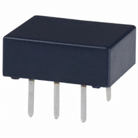
TK1-24V
Description
RELAY LOW PROFILE 2A 24VDC PCMNT
Manufacturer
Panasonic Electric Works
Series
TKr
Type
Miniature Relayr
Datasheet
1.TK1-5V.pdf
(6 pages)
Specifications of TK1-24V
Relay Type
General Purpose
Circuit
SPDT (1 Form C)
Contact Rating @ Voltage
2A @ 30VDC
Coil Type
Standard
Coil Current
11.3mA
Coil Voltage
24VDC
Control On Voltage (max)
18 VDC
Control Off Voltage (min)
2.4 VDC
Mounting Type
Through Hole
Termination Style
PC Pin
Relay Construction
Non-Latching
Contact Arrangement
SPDT
Coil Voltage Dc
24V
Contact Form
1 Form C
Voltage Rating (vdc)
220V
Dropout Volt (min)
2.4VDCV
Coil Resistance
2.133kohm
Pick-up Voltage (max)
18VDC
Maximum Power Rating
60W
Operate Time
3ms
Contact Current Rating
2A
Contact Material
Ag/Au Clad
Coil Suppression Diode
No
Push To Test Button
No
Led Indicator
No
Seal
Sealed
Product Height (mm)
4mm
Product Depth (mm)
9mm
Product Length (mm)
10.6mm
Operating Temp Range
-40C to 85C
Pin Count
6
Mounting Style
Through Hole
Package / Case
DIP
Lead Free Status / RoHS Status
Lead free / RoHS Compliant
Other names
255-1030
255-1030-5
255-1030
255-1030-5
255-1030
Available stocks
Company
Part Number
Manufacturer
Quantity
Price
Company:

Part Number:
TK1-24V
Manufacturer:
OMRON
Quantity:
12 000
Part Number:
TK1-24V
Manufacturer:
PANASON
Quantity:
20 000


TK
REFERENCE DATA
1. Maximum value of continuous carrying current
Test conditions:
Coil applied voltage: 110% of rated voltage
Continuous carrying current: 1,000 hours
4. Mechanical life
Tested sample: TK1-12V, 8 pcs.
Switching frequency: 30 Hz
6.-(1) Coil temperature rise
Tested sample: TK1-12V, 6 pcs.
Measured portion: Inside the coil
Ambient temperature: 25 C
7.-(1) Operate/release time characteristics
Tested sample: TK1-5 V, 50 pcs.
<Without diode>
100
60
50
40
30
20
10
90
80
70
60
50
40
30
20
10
2
1
0
0
4
3
2
1
0
0
Room temperature
80 90 100 110 120 130 140 150
40
80
10
0 A
1 A
2 A
Ambient temperature, C
50
Coil applied voltage, %V
Coil applied voltage, %V
Drop-out voltage
Pick-up voltage
No. of operations, 10
90
Release time
100
Operate time
60
100
77 F
70
110
1,000
80
120
Max.
Max.
Min.
Min.
4
85
10,000
90
Max.
Min.
Max.
Min.
All Rights Reserved © COPYRIGHT Panasonic Electric Works Co., Ltd.
2. Maximum switching capacity
5. Electrical life (DC load)
Tested sample: TK1-12V, 10 pcs.
Condition: 2 A 30 V DC resistive load, 20 cpm
Change of pick-up and drop-out voltage
6.-(2) Coil temperature rise
Tested sample: TK1-12V, 6 pcs.
Measured portion: Inside the coil
Ambient temperature: 70 C
7.-(2) Operate/release time characteristics
Tested sample: TK1-5 V, 50 pcs.
<With diode>
3.0
2.0
1.0
0.5
0.4
0.3
0.2
100
90
80
70
60
50
40
30
20
10
60
50
40
30
20
10
0
4
3
2
1
0
0
70 C
80 90 100 110 120 130 140 150
20
80
30
0 A
1 A
2 A
Pick-up voltage
Drop-out voltage
Coil applied voltage, %V
No. of operations, 10
Coil applied voltage, %V
Switching voltage, V
90
Operate time
Operate time
Operate time
50
100
DC load
158 F
Release time
Release time
Release time
100
110
200 300
120
4
Max.
Max.
Min.
Min.
Min.
10
Max.
Min.
Max.
Min.
3. Life curve
Change of contact resistance
8. Ambient temperature characteristics
Tested sample: TK1-12V, 5 pcs.
100
100
10
90
80
70
60
50
40
30
20
10
0
0
–40
–20
1
No . of operations, 10
0
Switching current, A
0
40
30
20
10
20
–10
–20
–30
–40
30 V DC resistive
40
temperature, C
2
60
Ambient
Drop-out
voltage
Pick-up
voltage
80
4
x
x
10
Max.
Min.
Related parts for TK1-24V
Image
Part Number
Description
Manufacturer
Datasheet
Request
R

Part Number:
Description:
RELAY LATCH LOPRO 2A 12VDC PCB
Manufacturer:
Panasonic Electric Works
Datasheet:
Part Number:
Description:
RELAY LATCH 2A 6VDC LOPRO PCB
Manufacturer:
Panasonic Electric Works
Datasheet:
Part Number:
Description:
RELAY LATCH 2A 4.5VDC LOPRO PCB
Manufacturer:
Panasonic Electric Works
Datasheet:
Part Number:
Description:
RELAY LATCH 2A 3VDC LOPRO PCB
Manufacturer:
Panasonic Electric Works
Datasheet:
Part Number:
Description:
RELAY LOW PROFILE 2A 5VDC PC MNT
Manufacturer:
Panasonic Electric Works
Datasheet:
Part Number:
Description:
RELAY LOW PROFILE 2A 12VDC PCMNT
Manufacturer:
Panasonic Electric Works
Datasheet:
Part Number:
Description:
RELAY LOW PROFILE 2A 9VDC PCB
Manufacturer:
Panasonic Electric Works
Datasheet:
Part Number:
Description:
RELAY LOW PROFILE 2A 4.5VDC PCB
Manufacturer:
Panasonic Electric Works
Datasheet:
Part Number:
Description:
RELAY LOW PROFILE 2A 3VDC PCB
Manufacturer:
Panasonic Electric Works
Datasheet:
Part Number:
Description:
RELAY LATCH LOPRO 2A 24VDC PCB
Manufacturer:
Panasonic Electric Works
Datasheet:

Part Number:
Description:
CONN SOCKET P4 .4MM 50POS SMD
Manufacturer:
Panasonic Electric Works
Datasheet:

Part Number:
Description:
CONN SOCKET .8MM 16POS SMD
Manufacturer:
Panasonic Electric Works
Datasheet:
Part Number:
Description:
CONN HEADER .8MM 16POS SMD
Manufacturer:
Panasonic Electric Works
Datasheet:
Part Number:
Description:
CONN SOCKET .8MM 20POS SMD
Manufacturer:
Panasonic Electric Works
Datasheet:
Part Number:
Description:
CONN SOCKET .8MM 20POS SMD
Manufacturer:
Panasonic Electric Works
Datasheet: