G6AK-234P-ST-US-DC5 Omron, G6AK-234P-ST-US-DC5 Datasheet - Page 4
G6AK-234P-ST-US-DC5
Manufacturer Part Number
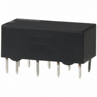
G6AK-234P-ST-US-DC5
Description
RELAY PC MNT DPDT 1A 5VDC
Manufacturer
Omron
Series
G6Ar
Datasheets
1.G6A-274P-ST-US_DC12_BY_OMR.pdf
(10 pages)
2.G2R-1-AC24.pdf
(19 pages)
3.G6AK-234P-ST-US-DC5.pdf
(9 pages)
4.G6A-234P-ST-US-DC12.pdf
(8 pages)
Specifications of G6AK-234P-ST-US-DC5
Coil Type
Latching, Dual Coil
Coil Current
36mA
Relay Type
General Purpose
Circuit
DPDT (2 Form C)
Contact Rating @ Voltage
1A @ 30VDC
Coil Voltage
5VDC
Control On Voltage (max)
3.5 VDC
Mounting Type
Through Hole
Termination Style
PC Pin
Contact Configuration
DPDT
Contact Current Max
2A
Contact Voltage Ac Nom
125V
Contact Voltage Dc Nom
30V
Coil Voltage Vdc Nom
5V
Coil Resistance
139ohm
Contact Form
2 Form C
Power Consumption
180 mW
Maximum Switching Current
2 A
Contact Rating
0.30 A at 125 VAC, 1 A at 30 VDC
Current, Rating
0.3⁄1 AAC⁄ADC
Function
Latching
Number Of Pins
10
Power, Rating
125⁄60 VA⁄W
Standards
UL, CSA
Termination
Solder
Voltage, Control
5 VDC
Voltage, Rating
125 VAC
Lead Free Status / RoHS Status
Lead free / RoHS Compliant
Control Off Voltage (min)
-
Lead Free Status / Rohs Status
Lead free / RoHS Compliant
Other names
G6AK234PSTUSDC5
Z749
Z749


G6A
Double-winding Latching, Low-sensitivity DPDT Relays
Double-winding Latching, Low-sensitivity 4PDT Relays
Note:
■
Note:
112
Rated voltage
Rated current
Coil resistance
Coil inductance
(H) (ref. value)
Must operate voltage
Must release voltage
Max. voltage
Power consumption
Rated voltage
Rated current
Coil resistance
Coil inductance
(H) (ref. value)
Must operate voltage
Must release voltage
Max. voltage
Power consumption
Load
Rated load
Contact material
Rated carry current
Max. switching voltage
Max. switching current
Max. switching power
Failure rate (reference value)
Load
Rated load
Contact material
Rated carry current
Max. switching voltage
Max. switching current
Max. switching power
Failure rate (reference value) (See note.)
Contact Ratings
1. The rated current and coil resistance are measured at a coil temperature of 23°C with a tolerance of ±10%.
2. Operating characteristics are measured at a coil temperature of 23°C.
3. The maximum voltage is the highest voltage that can be imposed on the relay coil.
P level:
This value was measured at a switching frequency of 60 operations/min and the criterion of contact resistance is 50 Ω . This value
may vary depending on the switching frequency and operating environment. Always double-check relay suitability under actual op-
erating conditions.
λ
60
= 0.1 x 10
Set
Reset
Set
Reset
Item
Item
Armature OFF
Armature ON
Armature OFF
Armature ON
Armature OFF
Armature ON
Armature OFF
Armature ON
–6
/operation
3 VDC
120 mA
25 Ω
0.015
0.01
0.01
0.015
70% max. of rated voltage
70% max. of rated voltage
150% of rated voltage at 23°C
Approx. 360 mW
3 VDC
120 mA
25 Ω
0.02
0.015
0.015
0.02
70% max. of rated voltage
70% max. of rated voltage
150% of rated voltage at 23°C
Approx. 360 mW
Resistive load
(cos φ = 1)
0.5 A at 125 VAC;
2 A at 30 VDC
Ag (Au-Alloy)
3 A
250 VAC, 220 VDC
2 A
125 VA, 60 W
0.01 mA at 10 mVDC
Resistive load
(cos φ = 1)
0.5 A at 125 VAC;
2 A at 30 VDC
Ag (Au-Alloy)
3 A
250 VAC, 220 VDC
2 A
125 VA, 60 W
0.01 mA at 10 mVDC
G6AK-274P-ST(40)-US/G6AK-474P-ST(40)-US
G6A-274P-ST(40)-US/474P-ST(40)-US
G6AU-274P-ST-US/G6AU-474P-ST-US
4.5 VDC
79.9 mA
56.3 Ω
0.04
0.025
0.025
0.04
4.5 VDC
79.9 mA
56.3 Ω
0.045
0.035
0.035
0.045
5 VDC
72.5 mA
69 Ω
0.05
0.035
0.035
0.05
5 VDC
72.5 mA
69 Ω
0.065
0.05
0.05
0.065
Inductive load
(cos φ = 0.4; L/R = 7 ms)
0.3 A at 125 VAC;
1 A at 30 VDC
1 A
62.5 VA, 30 W
Inductive load
(cos φ = 0.4; L/R = 7 ms)
0.25 A at 125 VAC;
1 A at 30 VDC
1 A
62.5 VA, 30 W
6 VDC
60 mA
100 Ω
0.09
0.075
0.075
0.09
6 VDC
60 mA
100 Ω
0.07
0.05
0.05
0.07
9 VDC
40 mA
225 Ω
0.18
0.14
0.14
0.18
9 VDC
40 mA
225 Ω
0.16
0.12
0.12
0.16
12 VDC
30 mA
400 Ω
0.3
0.23
0.23
0.3
12 VDC
30 mA
400 Ω
0.28
0.2
0.2
0.28
15 mA
1,600 Ω
1.2
0.82
0.82
1.2
24 VDC
15 mA
1,600 Ω
1.1
0.75
0.75
1.1
24 VDC
48 VDC
7.5 mA
6,400 Ω
4.4
3.2
3.2
4.4
48 VDC
7.5 mA
6,400 Ω
4
2.9
2.9
4
G6A
Related parts for G6AK-234P-ST-US-DC5
Image
Part Number
Description
Manufacturer
Datasheet
Request
R

Part Number:
Description:
LOW SIGNAL RELAY
Manufacturer:
Omron
Datasheet:
Part Number:
Description:
LOW SIGNAL RELAY
Manufacturer:
Omron
Datasheet:
Part Number:
Description:
LOW SIGNAL RELAY
Manufacturer:
Omron
Datasheet:
Part Number:
Description:
LOW SIGNAL RELAY
Manufacturer:
Omron
Datasheet:

Part Number:
Description:
RELAY PC MNT DPDT 1A 12VDC
Manufacturer:
Omron
Datasheet:
Part Number:
Description:
RELAY PC MNT DPDT 1A 24VDC
Manufacturer:
Omron
Datasheet:

Part Number:
Description:
RELAY, PCB, DPCO, 5V, LATCHING
Manufacturer:
Omron
Datasheet:
Part Number:
Description:
RELAY, PCB, DPCO, 12V, LATCHING
Manufacturer:
Omron
Datasheet:
Part Number:
Description:
LOW SIGNAL RELAY
Manufacturer:
Omron
Datasheet:
Part Number:
Description:
LOW SIGNAL RELAY
Manufacturer:
Omron
Datasheet:
Part Number:
Description:
LOW SIGNAL RELAY
Manufacturer:
Omron
Datasheet:
Part Number:
Description:
LOW SIGNAL RELAY
Manufacturer:
Omron
Datasheet:
Part Number:
Description:
LOW SIGNAL RELAY
Manufacturer:
Omron
Datasheet:
Part Number:
Description:
LOW SIGNAL RELAY
Manufacturer:
Omron
Datasheet:

Part Number:
Description:
G6S-2GLow Signal Relay
Manufacturer:
Omron Corporation
Datasheet: