G6KU-2F-RF DC9 Omron, G6KU-2F-RF DC9 Datasheet - Page 2
G6KU-2F-RF DC9
Manufacturer Part Number
G6KU-2F-RF DC9
Description
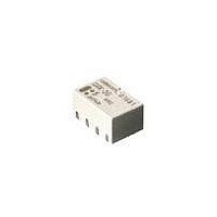
RELAY LOW SIGNAL SMD
Manufacturer
Omron
Series
G6K-RFr
Specifications of G6KU-2F-RF DC9
Relay Type
RF
Circuit
DPDT (2 Form C)
Contact Rating @ Voltage
1A @ 30VDC
Coil Type
Latching, Single Coil
Coil Current
11.3mA
Coil Voltage
9VDC
Control On Voltage (max)
6.75 VDC
Mounting Type
Surface Mount
Termination Style
Gull Wing
Contact Form
2 Form C
Power Consumption
100 mW
Isolation
20 dB to 30 dB at 1 GHz
Insertion Loss
0.2 dB at 1 GHz
Lead Free Status / RoHS Status
Lead free / RoHS Compliant
Control Off Voltage (min)
-
Lead Free Status / Rohs Status
Lead free / RoHS Compliant
Other names
G6KU-2F-RFDC9
G6KU2FRFDC9
G6KU2FRFDC9


■ Coil Data
G6K- 2.5 mm coil-contact terminal spacing, standard, non-latching (G6K-2F, G6K-2G, G6K-2P)
G6K- 3.2 mm coil-contact terminal spacing, non-latching (G6K-2F-Y, G6K-2G-Y, G6K-2P-Y)
G6KU- 3.2 mm spacing, single coil latching (G6KU-2F-Y, G6KU-2G-Y, G6KU-2P-Y)
Note: 1. The rated current and coil resistance are measured at a coil temperature of 23°C with a tolerance of ± 10%.
■ Characteristics
Note: 1. The contact resistance was measured with 10 mA at 1 VDC with a voltage-drop method.
68
3
4.5
5
6
9
12
24
3
4.5
5
6
9
12
24
Contact resistance (See note 1)
Operate (set) time (See note 2)
Release (set) time (See note 2)
Insulation resistance (See note 3)
Dielectric strength
Surge withstand voltage “-Y’ versions
Vibration
Shock
Ambient temperature
Humidity
Service life
Weight
Rated voltage
Rated voltage
(VDC)
(VDC)
2. The operating characteristics are measured at a coil temperature of 23°C unless otherwise specified.
3. Pick-up voltage will vary with temperature
4. The maximum voltage is the highest voltage that can be imposed on the relay coil instantaneously.
2. Values in parentheses are typical values unless otherwise stated.
3. The insulation resistance was measured with a 500-VDC megohmmeter applied to the same parts as those for checking the dielectric strength.
4. Data shown are of initial value.
Low Signal Relay
33.0
23.2
21.1
17.6
11.3
9.1
4.6
33.0
23.2
21.1
17.6
11.3
9.1
4.6
Rated current
Rated current
(mA)
(mA)
Standard versions
Mechanical durability 10 to 55 Hz; 5.0 mm double amplitude
Malfunction durability 10 to 55 Hz; 3.3 mm double amplitude
Mechanical durability 1,000 m/s
Malfunction durability 750 m/s
Mechanical
Electrical
91
194
237
341
795
1,315
5,220
91
194
237
341
795
1,315
5,220
Coil resistance
Coil resistance
G6K
(Ω)
(Ω)
100 mΩ max.
3 ms max. (Approx. 1.4 ms - standard. Approx. 1.2 ms - latching)
3 ms max. (Approx. 1.3 ms - standard. Approx. 1.2 ms - latching)
1,000 MΩ min. (at 500 VDC)
1,500 VAC for 1 minute between coil contacts
1,000 VAC for 1 minute between contacts of different poles
750 VAC for 1 minute between contacts of the same pole
2,500 V, (2 x 10 μs) between coil and contacts.
(Conforms to Bellcore specifications)
1,500 V, (10 x 160 μs) between coil and contacts / contacts of different and same polarity.
(Conforms to FCC Part 68)
-40°C to 70°C with no icing or condensation
5 to 85% RH
50,000,000 operations min. (at 36,000 operations per hour)
100,000 operations min. at rated load (at 1,800 operations per hour)
Approx. 0.7 g
80% max.
75% max.
Pick-up voltage
Set-up voltage
2
(approx. 75G)
2
(approx. 100G)
10% min.
75% min.
Dropout voltage
% of rated value
% of rated value
Reset voltage
150% max.
@ 23°C to 70°C
150% max.
@ 23°C to 70°C
Maximum voltage
Maximum voltage
Power consumption
Approx. 100
Power consumption
Approx. 100
(mW)
(mW)
Related parts for G6KU-2F-RF DC9
Image
Part Number
Description
Manufacturer
Datasheet
Request
R

Part Number:
Description:
RELAY LOW SIGNAL SMD
Manufacturer:
Omron
Datasheet:
Part Number:
Description:
SURFACE MOUNT RELAY
Manufacturer:
Omron
Datasheet:
Part Number:
Description:
SURFACE MOUNT RELAY
Manufacturer:
Omron
Datasheet:
Part Number:
Description:
SURFACE MOUNT RELAY
Manufacturer:
Omron
Datasheet:
Part Number:
Description:
SURFACE MOUNT RELAY
Manufacturer:
Omron
Datasheet:
Part Number:
Description:
SURFACE MOUNT RELAY
Manufacturer:
Omron
Datasheet:
Part Number:
Description:
Surface Mount Relay
Manufacturer:
Omron
Datasheet:

Part Number:
Description:
SURFACE MOUNT RELAY
Manufacturer:
Omron
Datasheet:
Part Number:
Description:
SURFACE MOUNT RELAY
Manufacturer:
Omron
Datasheet:
Part Number:
Description:
SURFACE MOUNT RELAY
Manufacturer:
Omron
Datasheet:
Part Number:
Description:
SMT Tape And Reel Relay
Manufacturer:
Omron
Datasheet:
Part Number:
Description:
SMT TAPE-N-REEL RELAY
Manufacturer:
Omron
Datasheet:
Part Number:
Description:
SMT TAPE-N-REEL RELAY
Manufacturer:
Omron
Datasheet:
Part Number:
Description:
SMT TAPE-N-REEL RELAY
Manufacturer:
Omron
Datasheet:
Part Number:
Description:
SMT Tape & Reel Relay
Manufacturer:
Omron
Datasheet: