AGN2004H Panasonic Electric Works, AGN2004H Datasheet - Page 3
AGN2004H
Manufacturer Part Number
AGN2004H
Description
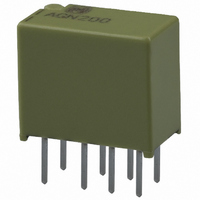
RELAY TELCOM DPDT 1A 4.5VDC PCB
Manufacturer
Panasonic Electric Works
Series
AGNr
Type
General Purpose Relayr
Specifications of AGN2004H
Relay Type
Telecom
Circuit
DPDT (2 Form C)
Contact Rating @ Voltage
1A @ 30VDC
Coil Type
Standard
Coil Current
31mA
Coil Voltage
4.5VDC
Control On Voltage (max)
3.38 VDC
Control Off Voltage (min)
0.45 VDC
Mounting Type
Through Hole
Termination Style
PC Pin
Brand/series
AGN Series
Contact Form
DPDT
Current, Rating
1⁄0.3 AAC⁄ADC
Dimensions
0.417 in. +⁄- 0.012 in. L x 0.224 in. +⁄- 0.12 in. W x 0.354 in. +⁄- 0.12 in. H
Function
General Purpose
Latch Type
Single Side Stable
Material, Contact
AgPd + Au Clad (Stationary), AgPd (Movable)
Number Of Pins
8
Power, Rating
30 W
Standards
UL, CSA
Termination
Solder
Voltage, Control
4.5 VDC
Voltage, Rating
125 VAC
Relay Construction
Non-Latching
Contact Arrangement
DPDT
Coil Voltage Dc
4.5V
Voltage Rating (vdc)
110V
Voltage Rating (vac)
125V
Dropout Volt (min)
0.45VDCV
Coil Resistance
145Ohm
Pick-up Voltage (max)
3.38VDC
Maximum Power Rating
30W/37.5VA
Operate Time
4ms
Contact Current Rating
1A
Contact Material
AgPd
Coil Suppression Diode
No
Push To Test Button
No
Led Indicator
No
Seal
Sealed
Product Height (mm)
9mm
Product Depth (mm)
5.7mm
Product Length (mm)
10.6mm
Operating Temp Range
-40C to 85C
Pin Count
8
Mounting Style
Through Hole
Package / Case
DIP
Lead Free Status / RoHS Status
Lead free / RoHS Compliant
Other names
255-1230
255-1230-5
255-1230
255-1230-5
255-1230
Available stocks
Company
Part Number
Manufacturer
Quantity
Price
Company:

Part Number:
AGN2004H
Manufacturer:
PANASONIC
Quantity:
30 000
Part Number:
AGN2004H
Manufacturer:
PANASONIC/松下
Quantity:
20 000


GN (AGN)
3) High sensitivity single side stable type
*Pulse drive (JIS C 5442-1996)
2. Specifications
Notes: *1 This value can change due to the switching frequency, environmental conditions, and desired reliability level, therefore it is recommended to check this with the
REFERENCE DATA
1. Max. switching capacity
Contact
Rating
Electrical
characteristics
Mechanical
characteristics
Expected life
Conditions
Unit weight
Nominal coil
Characteristics
1.5V DC
4.5V DC
12V DC
24V DC
voltage
3V DC
6V DC
9V DC
*2 Refer to 6. Conditions for operation, transport and storage mentioned in AMBIENT ENVIRONMENT.
1.0
0.3
actual load.
nominal voltage*
80%V or less of
(at 20 C
Arrangement
Initial contact resistance, max.
Contact material
Nominal switching capacity
Max. switching power
Max. switching voltage
Max. switching current
Min. switching capacity (Reference value)*
Nominal operating
power
Insulation resistance (Initial)
Breakdown voltage
(Initial)
Surge breakdown
voltage (Initial)
Temperature rise (at 20 C
Operate time [Set time] (at 20 C
Release time [Reset time] (at 20 C
Shock resistance
Vibration resistance
Mechanical
Electrical
Conditions for operation, transport and storage*
Max. operating speed (at rated load)
30
Set voltage
(Initial)
Contact voltage, V
68
DC resistive load
AC resistive load
F)
100
Single side stable
High sensitivity single side
stable type
1 coil latching
Between open contacts
Between contact and coil
Between contact sets
Between open contacts
Between contacts and coil
Functional
Destructive
Functional
Destructive
10%V or more of
nominal voltage*
Item
(at 20 C
Reset voltage
68
All Rights Reserved © COPYRIGHT Panasonic Electric Works Co., Ltd.
(Initial)
F)
68
68
68
2. Life curve
F)
F)
F)
1
100
50
40
30
20
10
0
[ 10%] (at 20 C
2
Nominal operating
0.2
66.7mA
33.3mA
22.2mA
16.7mA
11.1mA
current
8.3mA
5.0mA
2 Form C
Max. 100 m (By voltage drop 6 V DC 1A)
Stationary contact: AgPd+Au clad Movable contact: AgPd
1 A 30 V DC, 0.3 A 125 V AC (resistive load)
30 W (DC), 37.5 V A (AC) (resistive load)
110 V DC, 125 V AC
1 A
10 A 10 mV DC
140mW (1.5 to 12 V DC), 230mW (24 V DC)
100mW (1.5 to 12 V DC), 120mW (24 V DC)
Min. 1,000M
Measurement at same location as “Initial breakdown voltage” section.
750 Vrms for 1min. (Detection current: 10mA)
1,500 Vrms for 1min. (Detection current: 10mA)
1,000 Vrms for 1min. (Detection current: 10mA)
1,500 V (10 160 s) (FCC Part 68)
2,500 V (2 10 s) (Telcordia)
Max. 50 C
(By resistive method, nominal coil voltage applied to the coil; contact carrying current: 1A.)
Max. 4 ms [Max. 4 ms] (Nominal coil voltage applied to the coil, excluding contact bounce
time.)
Max. 4 ms [Max. 4 ms] (Nominal coil voltage applied to the coil, excluding contact bounce
time.) (without diode)
Min. 750 m/s
Min. 1,000 m/s
10 to 55 Hz at double amplitude of 3.3 mm (Detection time: 10 s.)
10 to 55 Hz at double amplitude of 5 mm
Min. 5
Min. 10
Ambient temperature:
(Single side stable, 1 coil latching type) –40 C to +85 C
(High sensitivity single side stable type) –40 C to +70 C
Humidity: 5 to 85% R.H. (Not freezing and condensing at low temperature)
20 cpm
Approx. 1 g
0.4
AC 125V
resistive load
Switching current, A
5
68
10
(1 A 30 V DC resistive), 10
DC 30V resistive load
0.6
7
F)
.035 oz
(at 180 cpm)
2
(Half-wave pulse of sine wave: 6 ms; detection time: 10 s.)
2
(at 500V DC)
0.8
(Half-wave pulse of sine wave: 6 ms.)
[ 10%] (at 20 C
Coil resistance
1.0
202.5
1,440
4,800
22.5
360
810
90
1.2
68
5
(0.3 A 125 V AC resistive) (at 20 cpm)
F)
Specifications
3. Mechanical life
Tested sample: AGN2004H, 15 pcs.
Operating speed: 180 cpm
Nominal operating
3.5
2.5
1.5
0.5
4
3
2
1
0
0
100mW
120mW
power
–40 F to +185 F
–40 F to +158 F
Drop-out voltage
10
Pick-up voltage
No. of operations, 10
Max. applied voltage
nominal voltage
nominal voltage
(at 20 C
30
150%V of
120%V of
4
68
F)
50
Max.
Min.
Max.
Min.
Related parts for AGN2004H
Image
Part Number
Description
Manufacturer
Datasheet
Request
R

Part Number:
Description:
RELAY TELCOM DPDT 1A 4.5VDC SMD
Manufacturer:
Panasonic Electric Works
Datasheet:

Part Number:
Description:
RELAY SLIM LATCH DPDT 12VDC PCB
Manufacturer:
Panasonic Electric Works
Datasheet:

Part Number:
Description:
RELAY TELCOM DPDT 1A 12VDC PCB
Manufacturer:
Panasonic Electric Works
Datasheet:
Part Number:
Description:
RELAY TELCOM DPDT 1A 24VDC SMD
Manufacturer:
Panasonic Electric Works
Datasheet:
Part Number:
Description:
RELAY TELCOM DPDT 1A 24VDC PCB
Manufacturer:
Panasonic Electric Works
Datasheet:

Part Number:
Description:
RELAY SLIM DPDT 1A 12VDC SMD
Manufacturer:
Panasonic Electric Works
Datasheet:
Part Number:
Description:
RELAY SLIM DPDT 1A 12VDC SMD
Manufacturer:
Panasonic Electric Works
Datasheet:
Part Number:
Description:
RELAY SLIM DPDT 1A 3VDC SMD
Manufacturer:
Panasonic Electric Works
Datasheet:
Part Number:
Description:
RELAY SLIM DPDT 1A 6VDC PCB
Manufacturer:
Panasonic Electric Works
Datasheet:
Part Number:
Description:
RELAY SLIM DPDT 1A 3VDC PCB
Manufacturer:
Panasonic Electric Works
Datasheet:

Part Number:
Description:
CONN SOCKET P4 .4MM 50POS SMD
Manufacturer:
Panasonic Electric Works
Datasheet:

Part Number:
Description:
CONN SOCKET .8MM 16POS SMD
Manufacturer:
Panasonic Electric Works
Datasheet:
Part Number:
Description:
CONN HEADER .8MM 16POS SMD
Manufacturer:
Panasonic Electric Works
Datasheet:
Part Number:
Description:
CONN SOCKET .8MM 20POS SMD
Manufacturer:
Panasonic Electric Works
Datasheet:
Part Number:
Description:
CONN SOCKET .8MM 20POS SMD
Manufacturer:
Panasonic Electric Works
Datasheet: