RP1-1.5V Panasonic Electric Works, RP1-1.5V Datasheet - Page 5
RP1-1.5V
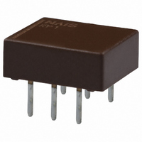
Manufacturer Part Number
RP1-1.5V
Description
RELAY HI FREQ 1.5VDC PCB MOUNT
Manufacturer
Panasonic Electric Works
Series
RPr
Datasheet
1.RP1-5V.pdf
(5 pages)
Specifications of RP1-1.5V
Relay Type
RF
Circuit
SPDT (1 Form C)
Contact Rating @ Voltage
0.1A @ 30VDC
Coil Type
Standard
Coil Current
93.8mA
Coil Voltage
1.5VDC
Control On Voltage (max)
1.13 VDC
Control Off Voltage (min)
0.15 VDC
Mounting Type
Through Hole
Termination Style
PC Pin
Lead Free Status / RoHS Status
Lead free / RoHS Compliant


RP
NOTES
1. Coil operating power
Pure DC current should be applied to the
coil. The wave form should be
rectangular. If it includes ripple, the ripple
factor should be less than 5%.
However, check it with the actual circuit
since the characteristics may be slightly
different. The nominal operating voltage
should be applied to the coil for more
than 20 ms to set/reset the latching type
relay.
2. Coil connection
When connecting coils, refer to the wiring
diagram to prevent mis-operation or
malfunction.
3. External magnetic field
Since RP relays are highly sensitive
polarized relays, their characteristics will
be affected by a strong external magnetic
field. Avoid using the relay under that
condition.
4. Packing direction
Relays are packed in a tube with the
orientation stripe (PIN NO. 1) toward the
green stopper.
Stopper (gray)
Orientation (indicates PIN No.1) stripe
Stopper (green)
All Rights Reserved © COPYRIGHT Panasonic Electric Works Co., Ltd.
5. Automatic mounting
To maintain the internal function of the
relay, the chucking pressure should
not exceed the values below.
Chucking pressure* in the direction A:
Chucking pressure* in the direction B:
Chucking pressure* in the direction C:
Please chuck the
Avoid chucking the center of the relay. In
addition, excessive chucking pressure to
the pinpoint of the relay should be
avoided.
*Value of chucking pressure is shown by the value of weight
pressed on the portion (4 mm
6. Soldering
Preheat according to the following
conditions.
Soldering should be done at 260±5°C
500±9°F
A
4.9 N {500 gf} or less
9.8 N {1 kgf} or less
9.8 N {1 kgf} or less
(6)
Temperature
(5)
(4)
Time
C
1
within 6 s.
2
3
B
• Direction A • Direction B • Direction C
120°C
.157 inch
Within 2 minute
portion.
248°F
dia.).
or less
6
1
5 4
2 3
mm
3
.118
6
.236
inch
For general cautions for use, please
refer to the “General Application
Guidelines”.
Related parts for RP1-1.5V
Image
Part Number
Description
Manufacturer
Datasheet
Request
R

Part Number:
Description:
RELAY HIGH FREQ 5VDC PC MNT
Manufacturer:
Panasonic Electric Works
Datasheet:
Part Number:
Description:
RELAY HIGH FREQ 12VDC PC MNT
Manufacturer:
Panasonic Electric Works
Datasheet:
Part Number:
Description:
RELAY HI FREQ 3VDC PCB MOUNT
Manufacturer:
Panasonic Electric Works
Datasheet:
Part Number:
Description:
RELAY HI FREQ 4.5VDC PCB MOUNT
Manufacturer:
Panasonic Electric Works
Datasheet:
Part Number:
Description:
RELAY HI FREQ 6VDC PCB MOUNT
Manufacturer:
Panasonic Electric Works
Datasheet:
Part Number:
Description:
RELAY HI FREQ 9VDC PCB MOUNT
Manufacturer:
Panasonic Electric Works
Datasheet:
Part Number:
Description:
RELAY HI FREQ 12VDC SELF-CLINCH
Manufacturer:
Panasonic Electric Works
Datasheet:
Part Number:
Description:
RELAY HI FREQ 4.5VDC SELF-CLINCH
Manufacturer:
Panasonic Electric Works
Datasheet:
Part Number:
Description:
RELAY HI FREQ 5VDC SELF-CLINCH
Manufacturer:
Panasonic Electric Works
Datasheet:
Part Number:
Description:
RELAY HIGH FREQ 24VDC PC MNT
Manufacturer:
Panasonic Electric Works
Datasheet:

Part Number:
Description:
Manufacturer:
Panasonic Electric Works
Datasheet:
Part Number:
Description:
Manufacturer:
Panasonic Electric Works
Datasheet:

Part Number:
Description:
CONN SOCKET P4 .4MM 50POS SMD
Manufacturer:
Panasonic Electric Works
Datasheet:
Part Number:
Description:
CONN SOCKET .8MM 16POS SMD
Manufacturer:
Panasonic Electric Works
Datasheet:
Part Number:
Description:
CONN HEADER .8MM 16POS SMD
Manufacturer:
Panasonic Electric Works
Datasheet: