HJ2-SFD-S Panasonic Electric Works, HJ2-SFD-S Datasheet - Page 8
HJ2-SFD-S
Manufacturer Part Number
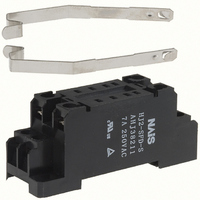
HJ2-SFD-S
Description
SOCKET TERM 2CHAN FOR HJ2 RELAYS
Manufacturer
Panasonic Electric Works
Series
HJr
Type
Socketr
Datasheet
1.HJ2-DC24V.pdf
(12 pages)
Specifications of HJ2-SFD-S
Number Of Positions
8
Mounting Type
DIN Rail
Termination Style
Screw Terminal
Features
Mounting Hardware
For Use With/related Products
HJ2 Relays
For Use With
HJ2-T-DC48V - RELAY PWR 10A 48VDC TEST/PLUG-INHJ2-T-DC110V - RELAY PWR 10A 110VDC TEST/PLUGINHJ2-T-AC48V - RELAY PWR 10A 48VAC TEST/PLUG-INHJ2-T-AC24V - RELAY PWR 10A 24VAC TEST/PLUG-INHJ2-T-AC220/240V - RELAY PWR 10A 240VAC PLUGINHJ2-T-AC200V - RELAY PWR 10A 200VAC TEST/PLUGINHJ2-T-AC12V - RELAY PWR 10A 12VAC TEST/PLUG-INHJ2-T-AC100V - RELAY PWR 10A 100VAC TEST/PLUGINHJ2-L-T-DC48V - RELAY PWR 10A 48VDC LED/TEST/PLGHJ2-L-T-DC110V - RELAY PWR 10A 110VDC PLUGINHJ2-L-T-AC48V - RELAY PWR 10A 48VAC PLUGINHJ2-L-T-AC24V - RELAY PWR 10A 24VAC PLUGINHJ2-L-T-AC220240V - RELAY PWR 10A 240VAC PLUGINHJ2-L-T-AC200V - RELAY PWR 10A 200VAC PLUGINHJ2-L-T-AC12V - RELAY PWR 10A 12VAC PLUGINHJ2-L-T-AC120V - RELAY PWR 10A 120VAC PLUGINHJ2-L-T-AC100V - RELAY PWR 10A 100VAC PLUGINHJ2-L-DC48V - RELAY PWR 7A 48VDC LED PLUG-INHJ2-L-DC24V - RELAY PWR 7A 24VDC LED PLUG-INHJ2-L-DC12V - RELAY PWR 7A 12VDC LED PLUG-INHJ2-L-DC110V - RELAY PWR 7A 110VDC LED PLUG-INHJ2-L-AC48V - RELAY PWR 7A 48VAC LED PLUG-INHJ2-L-AC24V - RELAY PWR 7A 24VAC LED PLUG-INHJ2-L-AC240V - RELAY PWR 7A 240VAC LED PLUG-INHJ2-L-AC200V - RELAY PWR 7A 200VAC LED PLUG-INHJ2-L-AC12V - RELAY PWR 7A 12VAC LED PLUG-INHJ2-L-AC120V - RELAY PWR 7A 120VAC LED PLUG-INHJ2-L-AC100V - RELAY PWR 7A 100VAC LED PLUG-INHJ2-DC48V - RELAY POWER 7A 48VDC PLUG-INHJ2-DC110V - RELAY POWER 7A 110VDC PLUG-INHJ2-AC48V - RELAY POWER 7A 48VAC PLUG-INHJ2-AC24V - RELAY POWER 7A 24VAC PLUG-INHJ2-AC200V - RELAY POWER 7A 200VAC PLUG-INHJ2-AC12V - RELAY POWER 7A 12VAC PLUG-INHJ2-AC100V - RELAY POWER 7A 100VAC PLUG-IN255-1684 - RELAY PWR W/TEST 10A 24V PLUGIN255-1683 - RELAY PWR W/TEST 10A 12V PLUGIN255-1682 - RELAY PWR W/TEST 10A 120VAC PLUG255-1681 - RELAY PWR LED&TEST 10A 24V PLUG255-1680 - RELAY PWR LED&TEST 10A 12V PLUG255-1679 - RELAY POWER 7A 24VDC PLUG-IN255-1678 - RELAY POWER 7A 12VDC PLUG-IN255-1677 - RELAY POWER 7A 240VAC PLUG-IN255-1676 - RELAY POWER 7A 120VAC PLUG-IN
Lead Free Status / RoHS Status
Lead free / RoHS Compliant
Other names
255-1838
HJ2-SFD-S
HJ2-SFD-S


HJ
NOTES
1. Coil applied voltage
Please refer to “RATING” about coil input
power supply.
2. LED display
Operation is displayed by the light
emitted from the LED. The LED may
remain briefly lit if voltage remains after
the relay opens.
3. Switching lifetime
The switching lifetime is defined under
the standard test condition specified in
the JIS* C 5442 standard (temperature
15 to 35 C
75%). Check this with the real device as it
is affected by coil driving circuit, load
type, activation frequency, activation
phase,ambient conditions and other
factors.
Also, be especially careful of loads such
as those listed below.
1) When used for AC load-operating and
the operating phase is synchronous.
Rocking and fusing can easily occur due
to contact shifting.
2) High-frequency load-operating
When high-frequency opening and
closing of the relay is performed with a
load that causes arcs at the contacts,
nitrogen and oxygen in the air is fused by
the arc energy and HNO
can corrode metal materials.
Three countermeasures for these are
listed here.
(1) Incorporate an arc-extinguishing
circuit.
(2) Lower the operating frequency
(3) Lower the ambient humidity
For Cautions for Use.
59 to 95
F, humidity 25 to
3
is formed. This
All Rights Reserved © COPYRIGHT Panasonic Electric Works Co., Ltd.
4. Usage, transport and storage
conditions
1) Temperature, humidity and pressure
during usage, storage and transport
(1) Temperature:
–40 to +70 C
(2) Humidity: 5 to 85% RH
(Avoid freezing and condensation.)
The humidity range varies with the
temperature. Use within the range
indicated in the graph below.
Temperature and humidity range for
usage, transport, and storage
(3) Atmospheric pressure: 86 to 106 kPa
2) Condensation
Condensation forms when there is a
sudden change in temperature under
high temperature and high humidity
conditions. Condensation will cause
deterioration of the relay insulation.
3) Freezing
Condensation or other moisture may
freeze on the relay when the
temperatures is lower than 0 C
causes problems such as sticking of
movable parts or operational time lags.
4) Low temperature, low humidity
environments
The plastic becomes brittle if the relay is
exposed to a low temperature, low
humidity environment for long periods of
time.
(Avoid freezing
when used at
temperatures
lower than
0 C
–40
–40
32
F)
Tolerance range
Temperature, C
–40 to +158 F
85
5
+32
0
(Avoid
condensation
when used at
temperatures
higher than
0 C
Humidity, %R.H.
32
F)
F
+158
70
32
F. This
5. Operation method for test button
1) Push and release 1 gently to confirm
relay switching.
2) To lock to one side turn 90 counter-
clockwise while pushing lock and turn 90
clockwise to release.
3) Do not use the test button for anything
other than testing, such as when
checking the circuit.
6. Diode characteristics
1) Reverse breakdown voltage: 1,000 V
2) Forward current:
7. Diode and CR built-in type
Since the diode and CR inside the relay
coil are designed to absorb the counter
emf, the element may be damaged if a
large surge, etc., is applied to the diode
and CR. If there is the possibility of a
large surge voltage from the outside,
please implement measures to absorb it.
8. Please connect DC coil types with
LED and built-in diode correctly by
verifying the coil polarity (“+” and “–
”). Connecting with reverse polarity
will cause the LED not to light and
damage the built-in diode due to its
specification.
For Lock
Release
Push
1
For Release
1 A
Related parts for HJ2-SFD-S
Image
Part Number
Description
Manufacturer
Datasheet
Request
R

Part Number:
Description:
SOCKET TERM 2CHAN FOR HJ2 RELAYS
Manufacturer:
Panasonic Electric Works
Datasheet:
Part Number:
Description:
Manufacturer:
Panasonic Electric Works
Datasheet:
Part Number:
Description:
Manufacturer:
Panasonic Electric Works
Datasheet:

Part Number:
Description:
CONN SOCKET P4 .4MM 50POS SMD
Manufacturer:
Panasonic Electric Works
Datasheet:
Part Number:
Description:
CONN SOCKET .8MM 16POS SMD
Manufacturer:
Panasonic Electric Works
Datasheet:
Part Number:
Description:
CONN HEADER .8MM 16POS SMD
Manufacturer:
Panasonic Electric Works
Datasheet:
Part Number:
Description:
CONN SOCKET .8MM 20POS SMD
Manufacturer:
Panasonic Electric Works
Datasheet:
Part Number:
Description:
CONN SOCKET .8MM 20POS SMD
Manufacturer:
Panasonic Electric Works
Datasheet:
Part Number:
Description:
CONN HEADER .8MM 20POS SMD
Manufacturer:
Panasonic Electric Works
Datasheet:
Part Number:
Description:
CONN SOCKET .8MM 22POS SMD
Manufacturer:
Panasonic Electric Works
Datasheet:
Part Number:
Description:
CONN SOCKET .8MM 30POS SMD
Manufacturer:
Panasonic Electric Works
Datasheet:
Part Number:
Description:
CONN HEADER .8MM 30POS SMD
Manufacturer:
Panasonic Electric Works
Datasheet:
Part Number:
Description:
CONN SOCKET .8MM 30POS SMD
Manufacturer:
Panasonic Electric Works
Datasheet:
Part Number:
Description:
CONN SOCKET .8MM 30POS SMD
Manufacturer:
Panasonic Electric Works
Datasheet:
Part Number:
Description:
CONN HEADER .8MM 30POS SMD
Manufacturer:
Panasonic Electric Works
Datasheet: