AQV210EH Panasonic Electric Works, AQV210EH Datasheet - Page 6
AQV210EH
Manufacturer Part Number
AQV210EH
Description
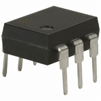
RELAY OPTO SPST-NO 130MA 6-DIP
Manufacturer
Panasonic Electric Works
Series
PhotoMOS™ AQVr
Datasheets
1.OAC415-L.pdf
(3 pages)
2.OAC415-L.pdf
(6 pages)
3.AQV210EHAX.pdf
(4 pages)
4.AQV214EH.pdf
(2 pages)
Specifications of AQV210EH
Circuit
SPST-NO (1 Form A)
Output Type
AC, DC
On-state Resistance
35 Ohm
Load Current
130mA
Voltage - Input
1.14VDC
Voltage - Load
0 ~ 350 V
Mounting Type
Through Hole
Termination Style
PC Pin
Package / Case
6-DIP (0.300", 7.62mm)
Application
For high speed inspection machines, telephone equipment, data communication equipment, computer
Capacitance, Output
45 pF (Typ.) @ 1 MHz
Contact Form
SPST-NO
Current, Rating
130 mA
Function
General Purpose
Number Of Pins
6
Package Type
Tube
Relay Type
Solid State
Resistance, On-state
23 Ohms (Typ.) @ 5 mA
Standards
cULus
Temperature, Operating, Maximum
85 °C
Temperature, Operating, Minimum
-40 °C
Termination
Through Hole
Voltage, Rating
350 VAC/VDC
Lead Free Status / RoHS Status
Lead free / RoHS Compliant
Other names
255-1145
255-1145-5
255-1145
255-1145-5
255-1145
Available stocks
Company
Part Number
Manufacturer
Quantity
Price

Part Number:
AQV210EH
Manufacturer:
NAIS
Quantity:
20 000
Company:
Part Number:
AQV210EHA
Manufacturer:
NAIS
Quantity:
5 510
Company:
Part Number:
AQV210EHA
Manufacturer:
NSC
Quantity:
5 510
Part Number:
AQV210EHA
Manufacturer:
PANASONIC/松下
Quantity:
20 000
Company:
Part Number:
AQV210EHAX
Manufacturer:
TI
Quantity:
15 420
Company:
Part Number:
AQV210EHAZ
Manufacturer:
PANASONIC
Quantity:
12 000


Notes: 1. E
APV1121S
APV2121S
APV2111V
APV1122
Type
2. Method of connecting the load at the output is divided into 3 types.
1
: Power source at input side; V
1
2
3
1
2
Schematic
IN
: Input voltage; I
6
4
4
3
configu-
Output
ration
1a
1a
All Rights Reserved © COPYRIGHT Matsushita Electric Works, Ltd.
F
AC/DC
: LED forward current; I
Load
DC
nection
Con-
—
—
Power MOSFET drive wiring diagram
Example of each input power supply and current limit resistors
(I
Power MOSFET drive wiring diagram
Example of each input power supply and current limit resistors
(I
IN
: Input current; V
F
F
E
E
= 10mA)
= 10mA)
1
1
E
E
1
1
I
I
F
F
I
I
F
F
1
2
3
1
2
R
R
L
: Load voltage; I
1
2
3
1
2
6
4
4
3
Wiring diagram
External
MOSFET
External
MOSFET
L
6
4
4
3
: Load current; R: Current limit resistor.
Load
Load
VL (AC, DC)
VL (AC, DC)
15V
24V
15V
24V
E
E
5V
5V
1
1
6
4
4
3
Approx. 1.4kΩ
Approx. 2.3kΩ
Approx. 1.4kΩ
Approx. 2.3kΩ
Approx. 380Ω
Approx. 380Ω
R
R
External
MOSFET
External
MOSFET
Load
Load
VL (DC)
VL (DC)
Related parts for AQV210EH
Image
Part Number
Description
Manufacturer
Datasheet
Request
R

Part Number:
Description:
RELAY OPTO AC/DC 350V 130MA 6DIP
Manufacturer:
Panasonic Electric Works
Datasheet:

Part Number:
Description:
Manufacturer:
Panasonic Electric Works
Datasheet:
Part Number:
Description:
Manufacturer:
Panasonic Electric Works
Datasheet:

Part Number:
Description:
CONN SOCKET P4 .4MM 50POS SMD
Manufacturer:
Panasonic Electric Works
Datasheet:
Part Number:
Description:
CONN SOCKET .8MM 16POS SMD
Manufacturer:
Panasonic Electric Works
Datasheet:
Part Number:
Description:
CONN HEADER .8MM 16POS SMD
Manufacturer:
Panasonic Electric Works
Datasheet:
Part Number:
Description:
CONN SOCKET .8MM 20POS SMD
Manufacturer:
Panasonic Electric Works
Datasheet:
Part Number:
Description:
CONN SOCKET .8MM 20POS SMD
Manufacturer:
Panasonic Electric Works
Datasheet:
Part Number:
Description:
CONN HEADER .8MM 20POS SMD
Manufacturer:
Panasonic Electric Works
Datasheet:
Part Number:
Description:
CONN SOCKET .8MM 22POS SMD
Manufacturer:
Panasonic Electric Works
Datasheet:
Part Number:
Description:
CONN SOCKET .8MM 30POS SMD
Manufacturer:
Panasonic Electric Works
Datasheet:
Part Number:
Description:
CONN HEADER .8MM 30POS SMD
Manufacturer:
Panasonic Electric Works
Datasheet:
Part Number:
Description:
CONN SOCKET .8MM 30POS SMD
Manufacturer:
Panasonic Electric Works
Datasheet:
Part Number:
Description:
CONN SOCKET .8MM 30POS SMD
Manufacturer:
Panasonic Electric Works
Datasheet:
Part Number:
Description:
CONN HEADER .8MM 30POS SMD
Manufacturer:
Panasonic Electric Works
Datasheet: