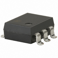
AQV221A Panasonic Electric Works, AQV221A Datasheet - Page 3

AQV221A
Manufacturer Part Number
AQV221A
Description
RELAY OPTO HIGH FREQ 80MA 6-SMD
Manufacturer
Panasonic Electric Works
Series
PhotoMOS™ AQVr
Specifications of AQV221A
Circuit
SPST-NO (1 Form A)
Output Type
AC, DC (RF)
On-state Resistance
35 Ohm
Load Current
80mA
Voltage - Input
1.14VDC
Voltage - Load
0 ~ 40 V
Mounting Type
Surface Mount
Termination Style
Gull Wing
Package / Case
6-SMD (300 mil)
Input Type
DC
Input Voltage (max)
1.5V
Output Voltage (max)
40V
Input Current (max)
50mA
Output Current
80mA
Isolation Voltage
1.5kV
Package Type
PDIP SMD
Output Device
MOSFET
Pin Count
6
Mounting
Surface Mount
Operating Temp Range
-20C to 80C
Operating Temperature Classification
Commercial
Rad Hardened
No
Lead Free Status / RoHS Status
Lead free / RoHS Compliant
Other names
255-1164
255-1164-5
255-1164
255-1164-5
255-1164
Available stocks
Company
Part Number
Manufacturer
Quantity
Price
Company:
Part Number:
AQV221A
Manufacturer:
NAIS
Quantity:
5 510
Company:
Part Number:
AQV221A
Manufacturer:
SIEMENS
Quantity:
5 510
Part Number:
AQV221A
Manufacturer:
NAIS
Quantity:
20 000
Company:
Part Number:
AQV221AX
Manufacturer:
PANASONIC
Quantity:
12 000
Notes: 1. E
AQW21(SOP)
AQY41(SOP)
AQV41(SOP)
AQW21
AQW22
AQW25
AQW27
AQY41
AQV41
AQV45
Series
Series
Series
Type
2. Method of connecting the load at the output is divided into 3 types.
1
: Power source at input side; V
1
2
1
2
3
1
2
3
4
Terminal 3 cannot be
used, since it is in the in-
ternal circuit of the relay.
Schematic
8
7
6
5
4
3
6
5
4
IN
: Input voltage; I
configu-
All Rights Reserved © COPYRIGHT Matsushita Electric Works, Ltd.
Output
ration
2a
1b
1b
AC/DC
AC/DC
AC/DC
Load
DC
DC
F
: LED forward current; I
nection
Con-
—
—
A
B
C
Can be also connected as 2 Form B type. (However, the sum of the continuous load current
should not exceed the absolute maximum rating.)
(1) Two independent 1 Form A use
(2) 2 Form A use
E
E
E
E
E
E
E
E
1
1
1
1
1
1
1
1
IN
: Input current; V
I
I
F
I
I
F
I
I
F
F
I
I
F
F
F1
F2
1
2
3
4
1
2
3
4
1
2
1
2
3
1
2
3
1
2
3
1
2
3
L
: Load voltage; I
6
5
4
6
5
4
6
5
4
6
5
4
8
7
6
5
8
7
6
5
4
3
Load
Load
Load
Load
I
I
I
I
L1
L2
L1
L2
I
L
I
I
Load
Load
Load
Load
L
I
Load
L
L
Wiring diagram
I
L
L
: Load current; R: Current limit resistor.
V
V
V
V
+
–
–
+
L
L
L
+
–
L
(DC)
(DC)
(AC,DC)
(DC)
V
V
V
V
V
L1
L2
L1
L2
L
(AC,DC)
(AC,DC)
(AC,DC)
(AC,DC)
(AC,DC)
8
7
6
5
8
7
6
5
4
3
6
4
6
5
5
4
6
5
4
I
I
I
I
L1
L2
L1
L2
Load
Load
Load
Load
Load
Load
Load
Load
Load
I
I
I
L
L
L
I
I
L
L
V
V
V
V
L
+
–
–
+
V
V
V
V
L
L
+
–
L
V
(AC,DC)
(DC)
(DC)
L1
L2
L1
L2
(DC)
L
(AC,DC)
(AC,DC)
(AC,DC)
(AC,DC)
(AC,DC)


