PR33MF51NSZF Sharp Microelectronics, PR33MF51NSZF Datasheet
PR33MF51NSZF
Specifications of PR33MF51NSZF


Related parts for PR33MF51NSZF


PR33MF51NSZF Summary of contents
Page 1
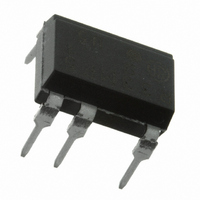
... PR33MF51NSZF Series ■ Description PR33MF51NSZF Series Solid State Relays (SSR) are an integration of an infrared emitting diode (IRED), a Phototriac Detector and a main output Triac. These devices are ideally suited for controlling high voltage AC loads with solid state reliability while providing 4kV isola- tion (V (rms)) from input to output ...
Page 2
... Internal Connection Diagram ■ Outline Dimensions 1. Through-Hole [ex. PR33MF51NSZF] ± 0.3 1.2 ± 0.20 1.05 SHARP Model No mark "S" Rank mark CSA mark Date code (2 digit) Anode mark Factory identification mark ± 0.50 9.66 ± 0.25 2.54 ± 0.1 0.5 Product mass : approx. 0.56g 3 ...
Page 3
... Please contact the local SHARP sales representative to see the actural status of the production. Rank mark Please refer to the Model Line-up table. 2nd digit Month of production Month Mark January 1 February 2 March 3 April 4 May 5 June 6 July 7 August 8 September 9 October O November N December D Japan 3 PR33MF51NSZF Series Sheet No.: D4-A03901EN ...
Page 4
... − dV/ √ 2 ·V D DRM 6V 100 Ω DC500V 60%RH ISO 6V 100 Ω 20mA PR33MF51NSZF Series Soldering area (T = 25˚C) a MIN. TYP. MAX. Unit 1.2 1.4 V − 10 μ A − − 100 μ A − − − − − − 100 V/ μ s − − − ...
Page 5
... Model Line-up Lead Form Through-Hole Shipping Sleeve Package 50 pcs/sleeve DIN − EN60747-5-2 Model No. PR33MF51NSZF PR33MF51YSZF PR33MF51NIPF PR33MF51YIPF Please contact a local SHARP sales representative to inquire about production status. SMT Gullwing Taping 1 000 pcs/reel Approved − 5 PR33MF51NSZF Series V Rank DRM [V] mark R Approved ...
Page 6
... Ambient temperature T Fig.2 RMS ON-state Current vs. Ambient Temperature 100 (˚C) a Fig.4 Minimum Trigger Current vs. Ambient Temperature 2 2.5 3 (V) F Fig.6 Relative Holding Current vs. Ambient Temperature 1 000 I =0.3A T(rms) 100 (˚ PR33MF51NSZF Series 0.3 0.2 0.1 0 − Ambient temperature T (˚ = =100 ...
Page 7
... ON-state voltage V Remarks : Please be aware that all data in the graph are just for reference and not for guarantee. Fig.8 Turn-on Time vs. Forward Current 100 1 PR33MF51NSZF Series V = =100Ω =25˚ Forward current I (mA) F Sheet No.: D4-A03901EN 100 ...
Page 8
... OUT Locate snubber circuit between output terminals I (rms) OUT (Cs = 0.022 μ Ω − T − opr ) must be 0.1mA or less F , increases faster than rated dV/dt, the Triac may turn on. To avoid this situa PR33MF51NSZF Series MIN. MAX. Unit 0.1 mA 240 V − I (rms)× − ...
Page 9
... Recommended Foot Print (reference) ● Standard Circuit Tr1 ✩ For additional design assistance, please review our corresponding Optoelectronic Application Notes. SMT Gullwing Lead-form 8.2 2.2 (Unit : mm) Load 2 8 SSR Line Surge absorption circuit (Snubber PR33MF51NSZF Series Sheet No.: D4-A03901EN ...
Page 10
... Please test the soldering method in actual condition and make sure the soldering works fi ne, since the im- pact on the junction between the device and PCB varies depending on the tooling and soldering conditions. Reflow 220˚C or more, 60s or less PR33MF51NSZF Series 4 (min) Sheet No.: D4-A03901EN ...
Page 11
... This product shall not contain the following materials banned in the RoHS Directive (2002/95/EC •Lead * , Mercury, Cadmium, Hexavalent chromium, Polybrominated biphenyls (PBB), Polybrominated diphenyl ethers (PBDE High melting temperature type solders (i.e. tin-lead solder alloys containing more than 85% lead) is exempted from the requirements. PR33MF51NSZF Series 11 Sheet No.: D4-A03901EN ...
Page 12
... MAX. 50pcs of products shall be packaged in a sleeve. Both ends shall be closed by tabbed and tabless stoppers. The product shall be arranged in the sleeve with its anode mark on the tabless stopper side. MAX. 20 sleeves in one case. Sleeve outline dimensions 12 6.7 PR33MF51NSZF Series 12 (Unit : mm) Sheet No.: D4-A03901EN ...
Page 13
... Direction of product insertion ±0.1 ±0.10 ±0.1 ±0.1 1.75 12.0 2 ±0.05 ±0.1 ±0.1 4.2 10.2 Dimensions List f b Pull-out direction 13 PR33MF51NSZF Series J I (Unit : mm ±0.1 +0.1 4.0 φ1.5 −0 (Unit : mm 17.5 ±1.5 ±1 ±0.5 φ330 φ100 φ13 ±1 2.0 ±0.5 2.0 ±0.5 φ ...
Page 14
... Measures such as fail-safe function and redundant design should be taken to ensure reliability and safety when SHARP devices are used for or in connection [N077] PR33MF51NSZF Series with equipment that requires higher reliability such as: --- Transportation control and safety equipment (i.e., aircraft, trains, automobiles, etc.) --- Traffi ...