CKRD2410 Crydom Co., CKRD2410 Datasheet - Page 2
CKRD2410
Manufacturer Part Number
CKRD2410
Description
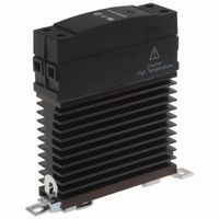
RELAY SSR SPST 10A@280VAC DIN MT
Manufacturer
Crydom Co.
Series
CKR24r
Specifications of CKRD2410
Termination Style
Screw Terminal
Circuit
SPST-NO (1 Form A)
Output Type
AC, Zero Cross
Load Current
10A
Voltage - Input
4 ~ 32VDC
Voltage - Load
24 ~ 280 V
Mounting Type
DIN Rail
Package / Case
SSR with Integrated Heatsink
Control Voltage Range
4 VDC to 32 VDC
Load Voltage Rating
280 V
Load Current Rating
10 A
Output Device
SCR
Mounting Style
DIN Rail
Relay Type
Solid State
Input Type
DC
Input Voltage (max)
32V
Output Voltage (max)
280(RMS)V
Input Current (max)
12mA
Output Current
10A
Isolation Voltage
4kV
Pin Count
4
Mounting
Din-Rail
Operating Temp Range
-40C to 80C
Operating Temperature Classification
Commercial
Rad Hardened
No
Lead Free Status / RoHS Status
Lead free / RoHS Compliant
On-state Resistance
-
Lead Free Status / Rohs Status
Compliant
Other names
CC1517
CKRD2410
CKRD2410
Available stocks
Company
Part Number
Manufacturer
Quantity
Price
Company:

Part Number:
CKRD2410
Manufacturer:
Crydom Co.
Quantity:
135
Company:
Part Number:
CKRD2410-10
Manufacturer:
Crydom Co.
Quantity:
135


GENERAL NOTES
All parameters at 25°C unless otherwise specified.
Off-State dv/dt test method per EIA/NARM standard RS-443, paragraph 13.11.1
Turn-on time for DC control random turn-on versions is 0.02msec.
Input circuitry for DC control version incorporates active current limiter.
PROTECTION
Over Current and Short Circuit
A solid state relay should be protected by a semiconductor fuse.
This type of fuse provides extremely fast opening of the circuit.
A fuse should be selected that has an I t let-through rating that
is less than the I t capability of the SSR, for the same duration.
Transient Over Voltage (P OPTION)
Select "P" option for internal overvoltage protection. At the
presence of high voltage transient the output of the SSR will be
triggered on, and the transient will be passed on to the load circuit
This is a non-degrading method of protection that ensures that
other SSR benefits are maintained.
Earth Bonding (Grounding)
The CKR heatsink is equiped with an earth bonding screw as is
required for Class 1 Protection, in accordance with EN 60950
(VDE 0804).
Terminations
Wire Size
Connections
Recommended Screw Torque Range
CKRINST
Rev. 100107
PAGE 2 OF 3
ORDERING INFORMATION
Part Number
Package Style
Input (Control) Type
Output Voltage
Output Current
CKR = CKR Series
20
30
10
D
A
24 = 24 - 280
48 = 48 - 530
60 = 48 - 660
= 4.0-32 Vdc
= 90-280 Vrms
= 18-36 Vrms (suffix E)
= 10 Amp
= 20 Amp
= 30 Amp
both input and output terminals.
minimum length of 0.4 inch (10mm).
• Maximum wire size of AWG#10 (3mm) on
• Ensure that wires ends are stripped to a
• 5.0-6.0 in lb (0.6-0.7 Nm) on input and output termination.
2
Vrms
Vrms
Vrms
2
CKR
A
2
4
Note: For detailed electrical specifications see Crydom individual data sheets.
3
0
E
P
+3/A1
1/L1
SOLID STATE
CONTACTOR
CKR SERIES
OUTPUT
2/T1
4/A2
1
MECHANICAL SPECIFICATIONS
(12.7)
0
(66.0)
(99.0)
.5
(22.5)
2.6
.890
3.9
MOUNTING
HOLE/SLOT
0.17 (4.3) DIA.
All dimensions are in inches (millimeters)
(81.9)
3.2
20
30
10
(88.9)
3.5
Current Rating 20A @ 25°C
20
Integrated Overvoltage Protection
Control Mode
AC Control Range
Blank = Zero Cross
Blank = Not Included
10
P
Blank = 90-280 Vrms
E
40
60
(81.3)
= Included
= Random
3.2
= 18-36 Vrms
80
High T emperature
Caution
!
HEAT SINK:
BLACK ANODIZED
ALUMINUM
Related parts for CKRD2410
Image
Part Number
Description
Manufacturer
Datasheet
Request
R

Part Number:
Description:
RELAY SSR 10-35MA INPUT 16 DIP
Manufacturer:
Crydom Co.
Datasheet:
Part Number:
Description:
RELAY SSR 3.5-10VDC INPUT 16 DIP
Manufacturer:
Crydom Co.
Datasheet:

Part Number:
Description:
RELAY SSR 5A 480VAC SIP
Manufacturer:
Crydom Co.
Datasheet:

Part Number:
Description:
RELAY SSR 12A 240VAC DC
Manufacturer:
Crydom Co.
Datasheet:

Part Number:
Description:
RELAY SSR 25A 240VAC DC
Manufacturer:
Crydom Co.
Datasheet:

Part Number:
Description:
POWER CONTROL SSR 15A DC IN
Manufacturer:
Crydom Co.
Datasheet:
Part Number:
Description:
RELAY SSR 125A 480VAC DC INPUT
Manufacturer:
Crydom Co.
Datasheet:
Part Number:
Description:
RELAY SSR 5A 380VAC AC OUT SIP
Manufacturer:
Crydom Co.
Datasheet:
Part Number:
Description:
RELAY SSR 10A 240VAC DC
Manufacturer:
Crydom Co.
Datasheet:
Part Number:
Description:
RELAY SSR 25A 120VAC AC
Manufacturer:
Crydom Co.
Datasheet:
Part Number:
Description:
RELAY SSR 10-35MA INPUT 16 DIP
Manufacturer:
Crydom Co.
Datasheet:
Part Number:
Description:
RELAY SSR 3.5-10VDC INPUT 16 DIP
Manufacturer:
Crydom Co.
Datasheet:
Part Number:
Description:
RELAY SSR AC 2A 120VAC PNL MNT
Manufacturer:
Crydom Co.
Datasheet:

Part Number:
Description:
RELAY SSR AC OUT 1CH 0.3A PCB
Manufacturer:
Crydom Co.
Datasheet:

Part Number:
Description:
RELAY SSR 3A PC MNT W/SNUBER
Manufacturer:
Crydom Co.
Datasheet: