G3VM-S2 Omron, G3VM-S2 Datasheet
G3VM-S2
Specifications of G3VM-S2
G3VMS2
Z160
Available stocks


Related parts for G3VM-S2


G3VM-S2 Summary of contents
Page 1
... G3VM Part Number Ordering Part Number G3VM-2 G3VM-2-S G3VM-3 G3VM-3-S G3VM-3L* G3VM-3L-S G3VM-V G3VM-V-S G3VM-6 G3VM-6-S G3VM-2F G3VM-2F- -S G3VM-3F G3VM-3F-S G3VM-3FL* G3VM-3FL-S G3VM-VF G3VM-VF-S G3VM-6F G3VM-6F-S G3VM-S5 G3VM-S5-S G3VM-S2 G3VM-S2-S G3VM-S3 G3VM-S3-S G3VM-W G3VM-W-S G3VM-WF G3VM-WF-S G3VM-SY G3VM-SY-S G3VM-SW G3VM-SW-S ...
Page 2
... I/O isolation voltage g AC for 1 minute AC for 1 second DC for 1 minute Temperature Operating temp. range limits limits Storage temp. range Fig. 1 Circuit connections for G3VM--3/3F, G3VM--3L/3FL, G3VM--6/6F, G3VM--S3 and G3VM--V/VF Connection A 1 LOAD G3VM-3/3F G3VM-3L/3FL 1 Form A ...
Page 3
... Initial I/O insulation Minimum resistance Load current limiting g =5mA t=5ms Note: =120mA for G3VM--3/3F, =120mA for G3VM--3L/3FL G3VM--V/VF Fig. 2 Timing test circuit for G3VM--3/3F, G3VM--3L/3FL, G3VM--6/6F, G3VM--S3 and G3VM--V/ Note: R =200 V =20V, =5mA G3VM-3/3F 1.0mA 3 ...
Page 4
... G3VM 3 MAXIMUM RATINGS AND ELECTRICAL CHARACTERISTICS (CONTINUED) G3VM-2/2F, G3VM-S2, G3VM-S5 Maximum ratings (at 23E unless otherwise stated) Part number Contact form Parameter Comments and conditions Package type Package type ------ Input (LED LED forward current Peak forward current 100 sec pulse ------ LED reverse voltage ...
Page 5
... Transfer Turn--on time See figure 4 characteristics Turn--off time I/O capacitance Typical Initial I/O insulation Minimum resistance Note: =120mA for G3VM--W/WF and G3VM--SW, ON Fig. 4 Timing test circuit for G3VM--W/WF, G3VM--SW, and G3VM-- Note: R =200 V =20V, =5mA G3VM-W/WF ...
Page 6
... Note: “G3VM” is not 2.5 min. printed on the (0.10 min.) actual product. G3VM- -3, G3VM-3L, G3VM- -V 7.12 0.25 (0.28 0.01) 0.5 0.1 Note: “G3VM” is not (0.02 0.004) printed on the 2.54 0.25 actual product. (0.10 0.01) G3VM-6 8 ...
Page 7
... Note: “G3VM” is not 1.2 0.15 printed on the (0.5 0.006) actual product. G3VM- -3F, G3VM-3FL, G3VM- -VF Note: “G3VM” is not 7.12 ±0.25 printed on the (0.28 ±0.01) actual product. 1.2 ±0.15 (0.05 ±0.006) 2.54 ±0.25 (0.10 ±0.01) Terminal Arrangement/ 9 ...
Page 8
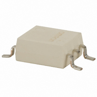
... G3VM-6F 8.64 0.25 (0.34 .0.010) Note: “G3VM” is not 0.5 printed on the (0.02) actual product. 2.54 (0.10) G3VM-S2 Note: “G3VM” is not printed on the actual product. 3.9 ±0.2 (0.15 ±0.008) 0.4 ±0.1 (0.02 ±0.004) 2.54 ±0.25 (0.10 ±0.01) 8 Terminal Arrangement/ ...
Page 9
... G3VM-S5 Note: “G3VM” is not printed on the actual product. 3.9 ±0.2 (0.15 ±0.008) 0.4 ±0.1 (0.02 ±0.004) 2.54 ±0.25 (0.10 ±0.01) G3VM-SW Note: “ ...
Page 10
... G3VM G3VM-SY Note: “G3VM” is not 9.4 ±0.25 printed on the (0.37 ±0.01) actual product. 2.54 ±0.25 (0.10 ±0.01) 0.4 ±0.1 (0.02 ±0.004) 10 Terminal Arrangement/ Internal Connections (Top View) 4.4 ±0.25 (0.17 ±0.01 2.1 max. (0.08 max.) 0. (0.006) 0.1 ±0.1 7 ±0.4 (0.004 ±0.004) (0.28 ± ...
Page 11
... G3VM Accessories Tube packing Standard nomenclature Tape packing When ordering, add “(TR)” to the ordering number, (e.g., G3VM--3F(TR)--S). Note: (TR) is not part of the relay model number and will not be marked on the relay. Part number Qty. per tube G3VM G3VM- -2F 50 ...
Page 12
... A 7.6 (0.30 3.15 0.04 0.51 0.02) D 7.5 (0.30 (0.08 0.02) F 12.0 (0.47) G 4.0 (0.16 (0.16 0.02) G3VM-S2(TR), G3VM- -S5(TR) Qty. per reel: 2,500 3.15 ±0.04) 13.5 ±0.5 (0.53 ±0.02) Symbol Dimension A 8.0 (0.31) B 4.0 (0.16 0.51 0.02 (0.08 0.02 ...
Page 13
... Dimension A 6.7 0.1 (0.26 0.04) B 12.0 0.1 (0.47 0.04 0.51 0.02) D 4.0 0.1 (0.16 0.04 (0.08 0.02) U 4.0 0.5 (0.16 0.02) G3VM-SW(TR), G3VM-SY (TR) Qty. per reel: 2,500 B C (12.99 ±0.08) E 17.5 ±0.5 (0.69 ±0.02) (0.85 ±0.04) Symbol Dimension A 12.0 (0.47 ...
Page 14
... Remarks -------- -------- -------- From reel hole to center -------- Total tolerance: +0.1/10, --0.3/10 pitches Total tolerance: +0.1/10, --0.3/10 pitches -------- G3VM 1.75 (0.07) from edge to reel hole 2.0 ±0.1 (0.08 ±0.004 16.0 ±0.3 (0.63 ±0.01) A 10.4 (0.41) ...
Page 15
... C G3VM-V/VF, G3VM--SY Min. Typ. Max. --- --- 48V 7.5mA 15mA 25mA --- --- 300mA --20 C --- 80 C G3VM-2/2F, G3VM--S2 G3VM 2/2F G3VM S2 G3VM-S5 G3VM S5 --0.5mA/ C --0.5mA/ C --1.2mA/ C --1.5mA/ C G3VM-3/3F, G3VM--3L/3FL, G3VM-3/3F, G3VM--3L/3FL, G3VM-6/6F G3VM-6/6F G3VM--S3 --0.5mA/ C --0.3mA/ C --1.2mA/ C --1.5mA/ C --1.2mA/ C --2.0mA/ C --1.6mA/ C --3 ...
Page 16
... ON THE OUTPUT TERMINALS If a spike voltage exceeding the absolute maximum rated value is 6 generated between the output terminals, insert a C-R snubber or Load clamping diode in parallel to the load as shown in the following cir- 5 cuit diagram to limit the spike voltage. Spike Voltage Protection Circuit Example G3VM ...
Page 17
... Relay is mounted automatically, otherwise the characteristics of the Relay may change. You must allow sufficient leeway in ratings and performance and provide proper fail-safe and other safety measures when using the G3VM in any of the following applications. Be sure also to consult with your OMRON representative before actually attempting any of these applications. 1. ...