DC-2R5E224U-E Elna America, DC-2R5E224U-E Datasheet - Page 32
DC-2R5E224U-E
Manufacturer Part Number
DC-2R5E224U-E
Description
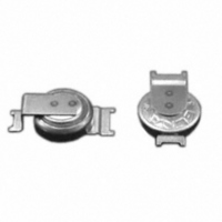
CAP DOUBLE LAYER .22F 2.5V COIN
Manufacturer
Elna America
Series
DCr
Specifications of DC-2R5E224U-E
Capacitance
220mF
Voltage - Rated
2.5V
Tolerance
-20%, +80%
Esr (equivalent Series Resistance)
100.00 Ohm
Lifetime @ Temp.
1000 Hrs @ 70°C
Mounting Type
Surface Mount
Package / Case
Surface Mount - Coin Style
Lead Spacing
0.079" (2.00mm)
Height
0.295" (7.50mm)
Size / Dimension
0.268" Dia (6.80mm)
Operating Temperature
-25°C ~ 70°C
Lead Free Status / RoHS Status
Lead free / RoHS Compliant
Other names
604-1006


CAT.No.2008/2009E ( 2008.10.1 )
ALUMINUM ELECTROLYTIC CAPACITORS
2. Do not apply excessive pressure to the capaci-
3. Soldering.
4. Handling after soldering.
5. Cleaning after Soldering
• Do not deform the capacitor for mounting.
• Make sure that the contact path of the capacitor
• Transient recovery voltage may be generated in the
• A PCB self-standing (snap-in) type capacitor should
• Do not set the automatic insertion machine to clinch
• Pay attention to the impact given by the compo-
• Do not dip the capacitor into melted solder.
• The soldering conditions
• Do not flux other part than the terminals.
• If there is a direct contact between the sleeve of
• When you use the capacitor with its sleeve touch-
• If the application is for extended use, understand
• After soldering, do not tilt, push down or twist the
• After soldering, do not hold the capacitor as a
• After soldering, do not hit the capacitor with any
• Recommended cleaning method
(1)cleaning solutions:
tor, its terminals or lead wires.
meets the hole pitch of the PCB before mounting.
capacitor due to dielectric absorption. If required,
a value of about 1 kΩ.
be pushed to the end (till there is no space) to the
PCB for mounting.
nent receptacles of the automatic insertion/mount-
ing machines and the product checker, and from
described in the catalog or product specifications.
metal part of another component such as a lead
ing directly to the PCB, excessive solder tempera-
sleeve to shrink or crack during the heat.
and manage the soldering characteristics to avoid
abnormal current caused by a contact failure
between the capacitor and the PCB.
capacitor.
handle to carry the PCB.
obstacle. If PCB’s are piled up for storage, the
capacitor should not touch another PCB or compo-
nent.
the dropped capacitor.
this voltage can be discharged with a resistor with
the capacitor lead wires too strong.
the centering operation.
The preliminar y heating and other conditions
the capacitor and the printed circuit pattern or a
wire, it may cause shrinkage of crack.
ture or excessive soldering time may cause the
(a) CLEANTHROUGH 710M, 750H, 750L
(b) PINEALPHA ST-100S
(c) Techno Care FRW-4~17
(d) Isopropyl alcohol (2-propanol)
Chip type : Please refer to 11 page.
small and large type : 260°C, 10 s (max.)
6. Fixing adhesives and coating materials.
1. Do not touch capacitor terminals with bare hands.
You may get electric shock or your hand may be
burnt. Discharge it with a 1 KΩ resistance before use
if necessary.
2. Do not short the capacitor terminals with a con-
Do not spill conductive solution including acid or alka-
line solution on the capacitor.
3. Periodical inspections should be established
• During cleaning, control the cleaning solution
• Do not use fixing adhesive or coating material
• Before applying the fixing adhesive or the coating
• Before applying the fixing adhesive or the coating
• Do not cover the whole surface of the sealed part
• Observe the description in the catalog or the prod-
• Recommended fixing adhesives and coating
• The following items should be checked:
(2)Cleaning conditions:
Other Cautions
ductor.
for the capacitors used in industrial appliances.
against contamination.
containing halogen-based solvent.
material, make sure that there is no remaining flux
or stains between the PCB and the sealed part of
the capacitor.
material, make sure that the detergent etc. has
dried up.
(terminal side) of the capacitor with the fixing ad-
hesive or the coating material.
uct specifications concerning the thermal stiffening
conditions of the fixing adhesive or the coating
material. (If there is no such description, contact
us.) When both discrete and SMT components are
on the same PCB, the fixing material for the SMT
components may cause crack, tear or shrinkage on
the external sleeve depending on the thermal
stiffening condition.
materials
Fixing adhesives : Cemedine 210, 501, 540, 545N, Diabond
DN83K, DA3288, Bond G103
Coating materials : Taffy TF1159, HumiSeal 1B66, 1A27NS
(a) The temperature of cleaning solution shall be
(b) Use immersion or ultrasonic waves within two
(c) After cleaning, capacitors and PCB’s shall
(d) After cleaning, do not keep capacitors in
less than 60°C.
minutes.
thoroughly be rinsed and dried with hot blast
for more than 10 minutes. The temperature of
such breeze should be less than the upper
category temperature.
cleaning solution atmosphere or air tight
containers.
NOTE
Design, Specifications are subject to change without notice.
Ask factory for technical specifications before purchase and/or use.
®
Related parts for DC-2R5E224U-E
Image
Part Number
Description
Manufacturer
Datasheet
Request
R

Part Number:
Description:
IC H-BRIDGE 7A DC MOTOR PDSO-20
Manufacturer:
Infineon Technologies
Datasheet:

Part Number:
Description:
DC 38..75Vi>15Vo 6.6A 99W
Manufacturer:
Power-One
Datasheet:

Part Number:
Description:
DC/DC Converters & Regulators 48W 24V 2A
Manufacturer:
POWER ONE

Part Number:
Description:
CONV DC-DC 50W 24VDC CASSETTE
Manufacturer:
POWER ONE
Datasheet:


Part Number:
Description:
CAP DOUBLE LAYER .10F 5.5V COIN
Manufacturer:
Elna America
Datasheet:

Part Number:
Description:
Supercapacitors V/MOUNT 5.5V 0.1F
Manufacturer:
Elna America
Datasheet:

Part Number:
Description:
CAP DOUBLE LAYER .07F 3.3V COIN
Manufacturer:
Elna America
Datasheet:

Part Number:
Description:
Vertical Chip Type Aluminum Electrolytic Capacitors
Manufacturer:
ELNA America, Inc.
Datasheet: