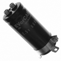
JJD0E607MSEC Nichicon, JJD0E607MSEC Datasheet

JJD0E607MSEC
Manufacturer Part Number
JJD0E607MSEC
Description
CAP EDLC 600F 2.5V SCREW TERM
Manufacturer
Nichicon
Series
EVerCAP® JDr
Datasheet
1.JJD0E607MSEC.pdf
(1 pages)
Specifications of JJD0E607MSEC
Capacitance
600F
Voltage - Rated
2.5V
Tolerance
±20%
Esr (equivalent Series Resistance)
13.5 mOhm
Lifetime @ Temp.
2000 Hrs @ 60°C
Mounting Type
Chassis Mount
Package / Case
Radial, Can - Screw Terminals
Lead Spacing
0.500" (12.70mm)
Height
3.346" (85.00mm)
Size / Dimension
1.378" Dia (35.00mm)
Operating Temperature
-25°C ~ 60°C
Voltage Rating
2.5 Volts
Operating Temperature Range
- 25 C to + 60 C
Dimensions
35 mm Dia. x 85 mm L
Leakage Current
0.5 mAmp
Product
Super Capacitors
Lead Free Status / RoHS Status
Lead free / RoHS Compliant
Other names
493-3320
ELECTRIC DOUBLE LAYER CAPACITORS "EVerCAP "
JD
( Code )
Item
Category Temperature Range
Rated Voltage Range
Rated Capacitance Range
Capacitance Tolerance
Leakage Current
Stability at Temperature
DCR
Endurance
Shelf Life
Marking
Voltage
The listed DCR value is typical and therefore not a guaranteed value.
Dimensions of terminal pitch(W) and length( R ) and Normal dia. of bolt (mm)
Rated
Dimensions
2.5V
High energy density.
Suitable for electric power storage.
Compliant to the RoHS directive (2002/95/EC).
Specifications
Bottom plate
(0E)
Drawing
Bottom plate
35, 40
51 and larger
35
40
51
63.5
*
D
1000
1300
2300
2500
4000
Cap.
600
800
950
( F )
L
h
H 0.5
+ MAX.
H 1
L
h
+ MAX.
Sleeve
12.7
18.8
26.0
28.6
series
Screw Terminal Type, High Energy Density Type
Sleeve
W
607
807
957
108
138
238
258
408
Cap.
code
Typical (m )
13.5
10.0
8.5
8.0
6.0
4.0
3.5
2.2
DCR
10
10
– 25 to + 60°C
2.5V
600 to 4000F
± 20% (20°C)
0.5C (mA) [C : Rated Capacitance (F)] (After 30 minutes' application of rated voltage. 2.5V)
Capacitance (
Refer to the list below.
The specifications listed at right shall be met when the capacitors
are restored to 20 °C after the rated voltage is applied for 2000 hours
at 60 °C.
The specifications listed at right shall be met when the capacitors
are restored to 20°C after storing the capacitors under no load
for 2000 hours at 60°C.
Printed with white color letter on black sleeve.
R
r 1
6
9
Hexagenal headed bolt
1
Hexagenal headed bolt
– 25°C) /
(mm)
3
3
3
3
See Note
35
40
51
63.5
M5(φ35)
M6(φ40)
M6
Case size
A 1
Capacitance ( +
P
+
(
Nominal of bolt
20°C
A
P
2
2
)
L (mm)
M5
M6
M6
M6
Pressure relief vent
*
085
105
135
105
135
135
150
150
DC internal resistance
T
20°C)
Pressure relief vent
100
Ref. Weight
130
160
210
210
250
450
500
800
70%
(g)
Performance Characteristics
Type numbering system (Example : 2.5V 600F)
J
1
DCR(–25°C) / DCR (+20°C)
Configuration
J
2
Cr (
(RoHS compliant)
D
3
111
SE
0
) Plating
Capacitance change
DCR
Leakage current
Capacitance change
DCR
Leakage current
4
The capacitance calculated from discharge time ( T) with constant
current ( i ) after 30minuite charge with rated voltage (2.5V).
The discharge current ( i ) is 0.01
The discharge time ( T) measured between 2V and 1V with
constant current.
The capacitance calculated bellow.
E
Note :
5
U
S
Symbol
Dimensions of mounting bracket
6
6
P
A
B
S
U
H
T
h
°
Leg shape
0
7
Capacitance (F) = i
D
7
8
Pressure relief vent
M
9
32.5
38.5
12
60
20
15
51
Capacitance tolerance ( 20% )
Rated capacitance ( 600F )
–
7.5
5.0
10
S
3-Legs
Rated voltage ( 2.5V )
E C
11 12 13 14
7
Within ±30% of the initial capacitance value
300% or less than the
Less than or equal to the initial specified value
Within ±30% of the initial capacitance value
300% or less than the
Less than or equal to the initial specified value
Configuration
63.5
38.1
43
14
60
25
20
–
8.0
5.0
Series name
Case dia. code
Type
T
35
24
29
45
10
30
15
10
7.0
3.5
rated capacitance (F).
35
40
51
63.5
D
initial value
initial value
( 35)
Code
27
32
48
10
45
17
12
C
D
G
40
F
7.0
3.5
2-Legs
( 35, 40)
( 51, 63.5)
CAT.8100Z
Code less
Code less
BN
BN
BB
51
33.2
40
14
30
25
15
–
6.0
4.5
Mounting bracket
2-leg brackets
No brackets
3-leg brackets
2-leg brackets
No bracket
63.5
40.5
46.5
14
30
35
20
(mm)
–
7.0
4.5