1249B B&K Precision, 1249B Datasheet - Page 22
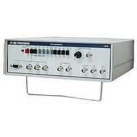
1249B
Manufacturer Part Number
1249B
Description
COLOR GENERATORNTSC/RGB
Manufacturer
B&K Precision
Type
NTSC Benchtopr
Specifications of 1249B
Patterns
Bar, Dot, Crosshatch, Raster
Connection Method
RCA, RF, S-Video
Power Source
105,130VAC
Signal Generator Type
NTSC Pattern
Supply Voltage Range
105V To 130V
External Height
86mm
External Width
290mm
External Depth
264mm
Frequency
30 Hz
Equipment Type
NTSC Pattern Generators
Lead Free Status / RoHS Status
na
Lead Free Status / RoHS Status
na
Other names
BK1249B


OPERATING INSTRUCTIONS
PRECAUTION AND TIPS
1.
2.
The most commonly encountered hazard in the use of this
instrument is “hot chassis” equipment. Always connect an
isolation transformer (such as the B & K Precision Model
TR-110 or 1604 Isolation Transformer or Model 1653A or
1655A AC Power Supply) between the wall outlet and any
“hot chassis” equipment under test. See the TEST
INSTRUMENT SAFETY section, steps 7 and 8 for more
information
The RF/IF and COMPOSITE VIDEO outputs of this
NTSC Generator are rated to withstand voltages of -35 to
+35 volts. All other outputs are rated to withstand -5 to +5
volts. The NTSC Generator must only be connected to
circuit points where the dc + ac peak voltage is within the
specified limit (±35 volts for the RF/IF and COMPOSITE
VIDEO outputs and ±5 volts for all other outputs). If in
doubt, make a voltage measurement first. Also take care to
prevent accidental contact with high voltage points.
To prevent electrical shock, observe the
precautions
INSTRUMENT SAFETY section, located on
the inside front cover of this manual.
listed
WARNING
in
the
TEST
22
3.
FAMILIARIZATION
To familiarize yourself with the operating controls, capabilities
and operating characteristics of the NTSC Generator, we
recommend that you connect it to a color television receiver
that is in proper operating condition and observe all the
patterns. An oscilloscope or waveform monitor may also be
used to observe all the waveforms produced.
INITIAL SET-UP
1.
2.
3.
All outputs have a source impedance of 75Ω. Therefore,
75Ω coaxial cable RG-59/U) is recommended for
interconnecting cables.
Connect the power cord of the NTSC Generator to a
120VAC, 60Hz outlet
Turn on the instrument by setting the POWER switch to
the ON position (engaged). The POWER indicator will
light when the power is on.
Apply power to the equipment under test and turn it on.
For “hot chassis” equipment, use an isolation transformer.