FLUKE-9040 Fluke Electronics, FLUKE-9040 Datasheet
FLUKE-9040
Specifications of FLUKE-9040


FLUKE-9040 Summary of contents
Page 1
... PN 2438546 April 2005 © 2005 Fluke Corporation. All rights reserved. Printed in China All product names are trademarks of their respective companies. 9040/9040UK Phase Rotation Indicator Users Manual ® ...
Page 2
... LIMITED WARRANTY AND LIMITATION OF LIABILITY This Fluke product will be free from defects in material and workmanship for one year from the date of purchase. This warranty does not cover fuses, disposable batteries, or damage from accident, neglect, misuse, alteration, contamination, or abnormal conditions of operation or handling. Resellers are not authorized to extend any other warranty on Fluke’ ...
Page 3
... Introduction.......................................................................................................... 1 Contacting Fluke ................................................................................................. 1 Unpacking the 9040 ............................................................................................ 2 Safety Information ............................................................................................... 3 Symbols............................................................................................................... 5 Elements of the 9040 .......................................................................................... 6 Determine the Rotary Field Direction .................................................................. 7 Maintaining the 9040 ........................................................................................... 8 Specifications ...................................................................................................... 9 Table of Contents Title i Page ...
Page 4
Table 1. Symbols ....................................................................................................... 5 Figure 1. The 9040/9040UK Phase Rotation Indicator............................................... 6 Title Title ii List of Tables Page List of Figures Page ...
Page 5
... Introduction The Fluke 9040 Phase Rotation Indicator (hereafter referred to, “the 9040” handheld instrument designed to detect the rotary field of three-phase systems. Contacting Fluke To contact Fluke, call one of the following telephone numbers: USA: 1-888-44-FLUKE (1-888-443-5853) Canada: 1-800-36-FLUKE (1-800-363-5853) Europe: +31 402-675-200 Japan: +81-3-3434-0181 ...
Page 6
Users Manual Unpacking the 9040 The 9040 ships with the following items: • 3 pieces self-retaining test probes (black) • Alligator clip • Users Manual If an item is damaged or missing, contact the place of purchase immediately. 2 ...
Page 7
Safety Information A WCaution identifies conditions and actions that may damage the 9040. A XWWarning identifies conditions and actions that pose hazard(s) to the user. To avoid possible electric shock or fire, do the following: • Read the following safety ...
Page 8
Users Manual • When using the probes, keep fingers away from probe contacts. Keep fingers behind the finger guards on the probes. • Measurements can be adversely affected by impedances of additional operating circuits connected in parallel or by ...
Page 9
Symbols The following symbols appear on the 9040 or in this manual. Y Risk of electric shock Risk of Danger. Important information. W See manual. X Hazardous voltage. Equipment protected by double or T reinforced Insulation Table 1. Symbols J ...
Page 10
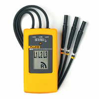
Users Manual Elements of the 9040 Indicators, buttons, and jacks are shown in Figure 1. Figure 1. The 9040/9040UK Phase Rotation Indicator 6 Test lead input jack L1, L2, L3 Indicators Clockwise Rotation LCD Indicator Counter-Clockwise RotationLCD Indicator Brief ...
Page 11
Determine the Rotary Field Direction To determine the rotary field direction: 1. Connect the test probes to the end of the test leads. 2. Connect the test probes to the three mains phases. 3. The green ON indicator shows that ...
Page 12
Users Manual Maintaining the 9040 To avoid damaging the 9040: • Do not attempt to repair or service the 9040 unless qualified to do so. • Make sure that the relevant calibration, performance test, and service information is being ...
Page 13
Specifications Environmental Operating Temperature 0 °C to +40 °C Pollution Degree 2 Type of Protection IP 40 Mechanical Specifications Size 124 (4.9 x 2.4 x 1.1 in) Weight 200 g (0.44 lbs) Safety Specifications Electrical ...
Page 14
Users Manual 10 ...