AT-1000 Amprobe, AT-1000 Datasheet - Page 7
AT-1000
Manufacturer Part Number
AT-1000
Description
ADVANCED WIRE TRACER
Manufacturer
Amprobe
Series
AT-1000r
Specifications of AT-1000
Voltage Range
0 ~ 300V
Current Rating
14 mA with No LEDs On/33 mA with LEDs On
Display Type
LED
Frequency
17 kHz
Measured Components
Advanced Wire Tracer
Voltage
0 V to 300 V
Lead Free Status / Rohs Status
Lead free / RoHS Compliant
Other names
2731097
705-1018
705-1018


2.
3.
4.
5.
6.
7.
8.
9.
10.
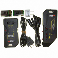
UNPACkINg ANd INSPECTIoN
ComPoNENT dESCRIPTIoN
R1000 Receiver
The R1000 contains two built-in detectors that are tuned to pick-up the 17khz signal generated
by the x1000. The detector is selected by the Mode Switch. The “open” position selects the
electrostatic (voltage potential) detector. The “CURRenT” position selects the electromagnetic
(current) detector. The selection of detector depends on the condition of the circuit to be traced.
The electromagnetic detector is set in one direction within the R1000 housing. The manner
in which the receiver is held, and the direction in which the detector is pointed, will vary the
amount of signal that is displayed and give the user an indication of the direction of the wire
being traced. This is particularly evident when the R1000 is in the “CURRenT” Mode. pointing
the receiver perpendicular to the wire, so that the front label faces the direction of the wire, will
yield the maximum signal displayed.
This equipment should only be used by trained professionals who are familiar with electrical
hazards.
Wear lineman gloves, safety glasses, and protective clothing at all times.
do not attempt to replace or remove the battery in the x1000 Transmitter until x1000 is
removed from the circuit and the cord set test leads are removed from the x1000 transmitter.
Always inspect the components and accessories for damage and proper operation befoRe
using. Replace any damaged components.
before connecting the x1000 Transmitter to a circuit, verify that the voltage, at the intended
point of contact, does not exceed 300VAC/dC.
Store the components in the case when not in use.
Remove the battery from the R1000 Receiver and x1000 Transmitter if the components will
not be in use for a long period of time.
before proceeding with any testing, confirm the x1000 is functioning correctly by switching
the x1000 to the “on” position. The battery indicator should flash. if the battery indicator
remains “off”, replace the battery.
Connections to the test circuit should be made after insertion of test leads into x1000.
AT-1000 (US version)
1 x R1000 Receiver
1 x x1000 Transmitter
1 x C2901 Cordset
1 x C2902 Cordset
1 x Ad-1 Adapter
1x instruction Manual
1x Soft Carrying case
2 x 9V battery
AT-1000E (Europe version)
1 x R1000 Receiver
1 x x1000 Transmitter
2 x Test probes (in set eU-200)
2 x Crocodile clips (in set eU-200)
2 x Test leads (in set eU-200)
1 x. instruction Manual
1 x hard carrying case
2 x 9V battery
6