HT-0095 FCI, HT-0095 Datasheet
HT-0095
Specifications of HT-0095


HT-0095 Summary of contents
Page 1
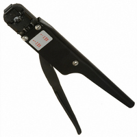
... Mini PV Receptacles 22-32 AWG Crimping Hand Tool FCI MANUAL P/N 415988-001 FCI Electronics Issued: (03/12/99) Rev. 05/18/06 EC V06-0481 HT-0095 Tool P/N HT-0095 PDM: Rev:C STATUS: Manual Part No. 415988-001 Page Revision C Released . Printed: Feb 09, 2009 ...
Page 2
... FCI Electronics Issued: (03/12/99) Rev. 05/18/06 EC V06-0481 HT-0095 Manual Part No. 415988-001 Page Revision C PDM: Rev:C Released STATUS: . Printed: Feb 09, 2009 ...
Page 3
... Anvil Installation ............................................................................................................ 11 Wire and Insulation Barrel Crimpers and Tonker Removal ........................................... 12 Wire and Insulation Barrel Crimpers and Tonker Installation ....................................... 13 Holding Pin Removal ..................................................................................................... 13 Holding Pin Installation .................................................................................................. 14 Crimp Height Adjustment ........................................................................................................ 15 Spare Parts Parts Ordering Information ........................................................................................ 16 Hand Tool Repair Policy ............................................................................................ 17 Recommended Spare Parts ......................................................................................... 17 Reference Documents ...
Page 4
... The top group consists of those parts, which remain stationary with the frame. The bottom group contains those parts, which move with the lever. The HT-0095 is equipped with tooling for crimping two different ranges of wire sizes. These are identified as "A" and "B" plate affixed to the hand tool frame. The " ...
Page 5
... Single Wire 28-32 AWG or Two Wires 30-32 AWG ……………………..0.66-0.71 mm (0.026-0.028 in.) Insulation Barrel Crimp Height: • Discrete Application …………………………2.84 mm (0. 112 in.) Max. • Latch and Rod Housing Applications … ...
Page 6
... If the terminal and the tooling are not compatible, damage to the tooling could result. If you wish to use a terminal with a part number other than the one that was ordered for the HT-0095, check with your distributor or with FCI Electronics to be sure that the new terminal number is compatible with your hand tool ...
Page 7
... Release the lever to open the hand tool and remove the crimped terminal from the holding pin by lightly pulling straight out on the wire. The crimp height for this hand tool was factory adjusted. Any random changes to this adjustment could cause a defective crimp or damage to the tooling. ...
Page 8
... Check that the spring was not dislodged from the disconnect (box) portion of the terminal. • Check that the wire barrel seam is even and tightly closed. Next, obtain a crimp height micrometer and measure the areas of the terminal shown in Figure 5. If the crimp heights do not meet the specifications listed in “Specifications” on page 5, refer to the section for proper adjustment procedures of crimp height on page 15 ...
Page 9
... Flashings formed on the bottom of the wire barrel are unequal or abnormal. 5. Insulation bulges between wire and insulation barrels. 6. Insulation bulges around insulation barrel. FCI Electronics Issued: (03/12/99) Rev. 05/18/06 EC V06-0481 TROUBLESHOOTING Receptacles ™ Possible Cause Terminal is not properly position in crimping area ...
Page 10
... Using a 7/64-inch Allen wrench, remove the cap screw securing the anvil holder assembly to the hand tool (see Figure 7). Then remove the anvil holder assembly. 3. Remove the cap screw(s) and defective anvil(s) from the anvil holder assembly (see Figure 8). FCI Electronics Issued: (03/12/99) Rev. 05/18/06 EC V06-0481 ...
Page 11
... Figure 10). Then rotate the collar about 1/2-turn counterclockwise. 3. Reinstall the anvil holder onto the hand and tighten the attaching cap screw. To prevent the anvils from being damaged during alignment, place a piece of paper, plastic bag material, or cellophane over the anvils ...
Page 12
... Then tighten the anvil cap screw(s). 5. Open the hand tool and remove the protective covering from the anvils. NOTE: The adjusting collar remains unlocked for further adjustment of the crimp height. 6. Crimp a terminal to the proper size wire. Then inspect the terminal and measure the wire barrel crimp height as described in Section II, paragraph B ...
Page 13
... To align the tooling, close hand tool completely and hold it in its closed position. Tighten the two 4-40 cap screws (9) to secure the crimpers to their holder. Then tighten the 6-40 cap screw (13), which secures the crimper holder to the hand tool frame ...
Page 14
... Re-install the two guides pins (15), "0" rings (16), and the two holding spring’s (17). 4. Re-install the terminal holder (10) to the anvil holder (4), and tighten the two 2-56 setscrews (12) in the anvil holder (4) onto the flats of the guide pins (15). 5. Crimp a terminal to a proper-sized wire, and inspect the terminal as described in Section II, paragraph B ...
Page 15
... Insert the turned-down end of the 3/32-inch Allen wrench or a pin, approximately 1/16-inch in diameter, into one of the holes in the adjusting collar (see Figure 14). Then rotate the collar about 5 degrees counterclockwise to increase crimp height or clockwise to decrease crimp height. NOTE: A 5-degree rotation of the adjusting collar will change the crimp height 0.002-inch. FCI Electronics Issued: (03/12/99) Rev ...
Page 16
... Reinstall the anvil holder assembly onto the hand tool and loosely tighten the attaching cap screw. Then slowly close the hand tool all the way and tighten the cap screw. 5. Crimp a terminal to the proper size wire and check the wire barrel crimp height of the crimped terminal. If crimp height is not as specified, turn the adjusting collar an additional 5 degrees. ...
Page 17
... FCI Electronics charges a standard rate to repair any hand tool not under warranty. Phone Toll Free 1- 800-237-2374 to obtain a Return Material Authorization number (RMA), shipping instructions and the current cost of repair. FCI will repair the hand tool and return it to you by the fastest means possible. Parts List for Figure 15. HT-95 Hand Tool Parts Index No. ...
Page 18
... Figure 15. HT-95 Hand Tool Parts FCI Electronics Issued: (03/12/99) Rev. 05/18/06 EC V06-0481 Manual Part No. 415988-001 Page Revision C PDM: Rev:C Released STATUS: . Printed: Feb 09, 2009 ...