63811-6800 Molex Inc, 63811-6800 Datasheet - Page 2
63811-6800
Manufacturer Part Number
63811-6800
Description
TOOL CRIMP FOR .084 CONTACTS
Manufacturer
Molex Inc
Series
PremiumGrade™, MLX™r
Type
Crimp Toolr
Datasheets
1.64016-0201.pdf
(1 pages)
2.63811-7500.pdf
(24 pages)
3.63811-6800.pdf
(6 pages)
4.63811-6800.pdf
(2 pages)
Specifications of 63811-6800
Tool Type
Hand Crimper
Features
Side Entry, Ratchet
Product
Crimping, Stripping & Cutting Tools & Drills
Crimp Size
20AWG To 14AWG
Crimp Application
Contacts
Rohs Compliant
NA
Lead Free Status / RoHS Status
Not applicable / Not applicable
For Use With/related Products
Rectangular Contacts, 14-20 AWG
For Use With
WM1271CT - CONN TERM FEMALE 14-20AWG TINWM1271TR - CONN TERM FEMALE 14-20AWG TINWM1271 - CONN TERM FEMALE 14-20AWG TINWM1270 - CONN TERM MALE 14-20AWG TIN
Lead Free Status / Rohs Status
Lead free / RoHS Compliant
Other names
063811-6800
063811-6800-P
0638116800
0638116800-P
63811-6800-P
638116800
638116800-P
WM9009
063811-6800-P
0638116800
0638116800-P
63811-6800-P
638116800
638116800-P
WM9009


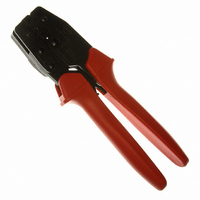
Hand Crimp Tool for MLX™ Pin and Socket Crimp Terminals
Doc No: ATS-638116800
Revision: B
CONDITIONS:
OPERATION
After crimping, the conductor profiles should measure the following (see notes on page 5).
CAUTION: Install only Molex terminals listed above with this tool. Do not crimp hardened objects as
damage can occur to the tool or die.
Open the tool by squeezing the handles together, at the end of the closing stroke, the ratchet mechanism will
release the handles, and the hand tool will spring open.
Crimping Terminals
1. Select the desired terminal listed in the preceding charts.
2. Swing the terminal locator away from the crimp tool shown in Figure 2.
3. When using the locator, press down on the wire stop on the locator as
4. Return the locator to its original position. Insert the proper wire over the
5. Compress the terminal by squeezing the tool handles until the ratchet mechanism cycle has been completed.
Note: The tamper proof ratchet action will not release the tool until it has been fully closed.
Some terminals with large insulation grips may interfere with the crimp
tooling when swinging the locator into position. The terminal must then be
loaded into the locator in the closed/crimp position.
shown in Figure 2. Insert the proper terminal into the proper nest opening.
Make sure when choosing the nest opening, it will correspond with the A,
B, or C profile on the hand tool.
terminal. Some large O.D. wires may need to be placed into the terminal before closing the tool. Gently touch
the wire stop with the end of the wire. See Figure 3.
Release handles to open the jaws.
Series No.
Terminal
42023
42024
To Achieve IPC-A-620 Class 2 Crimps, the following over-all wire insulation diameter ranges are recommended:
AWG
Wire Size
14
16
18
20
14
16
18
20
2.00 1.55-1.65 .061-.065 2.71
1.30 1.40-1.50 .055-.059 2.50
0.80 1.30-1.40 .051-.055 2.24
0.50 1.30-1.40 .051-.055 2.23
2.00 1.55-1.65 .061-.065 2.71
1.30 1.40-1.50 .055-.059 2.50
0.80 1.30-1.40 .051-.055 2.24
0.50 1.30-1.40 .051-.055 2.23
mm
2
Release Date: 09-18-06
Revision Date: 03-28-08
mm
Height (Ref.)
Conductor Crimp
Profile C: 1.52-2.70mm (.060-.106 inch)
Profile A: 2.30-3.30mm (.090-.130 inch)
Profile B: 1.90-2.90mm (.075-.114 inch)
In.
Width (Ref.) Height (Ref.) Width (Ref.)
mm
.107
.098
.088
.088
.107
.098
.088
.088
In.
UNCONTROLLED COPY
3.24
2.88
2.40
2.38
3.24
2.88
2.40
2.38
mm
Insulation Crimp
.127
.113
.094
.093
.127
.113
.094
.093
In.
3.13
3.10
2.83
2.79
3.13
3.10
2.83
2.79
mm
LOCATOR
.123 222.4 50.00 X
.122 133.4 30.00
.111
.110
.123 222.4 50.00 X
.122 133.4 30.00
.111
.110
In.
JAWS OPEN
Pull Force
88.9 20.00
57.8 13.00
88.9 20.00
57.8 13.00
Minimum
N
Lb. A B C
Profile
Figure 1
X
X
Page 2 of 6
X
X
X
X