63811-4400 Molex Inc, 63811-4400 Datasheet - Page 2
63811-4400
Manufacturer Part Number
63811-4400
Description
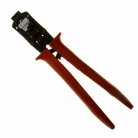
TOOL HAND CRIMP 14-22AWG
Manufacturer
Molex Inc
Series
MX150L™r
Type
Crimpersr
Datasheets
1.19417-0119.pdf
(7 pages)
2.64016-0201.pdf
(1 pages)
3.63811-7500.pdf
(24 pages)
4.63811-4400.pdf
(5 pages)
5.63811-4400.pdf
(2 pages)
Specifications of 63811-4400
Features
Side Entry, Ratchet
Tool Type
Hand Crimper
Product
Crimping, Stripping & Cutting Tools & Drills
Fits Cable/wire
22-14 AWG
Crimp Size
22AWG To 14AWG
Rohs Compliant
NA
Lead Free Status / RoHS Status
Not applicable / Not applicable
For Use With/related Products
Rectangular Contacts, 14-22 AWG
For Use With
WM17430 - CONN TERM MALE 14-16AWG TINWM17429 - CONN TERM MALE 18-22AWG TINWM17428 - CONN TERM FEMALE 14-16AWG TINWM17427 - CONN TERM FEMALE 18-22AWG TIN
Lead Free Status / Rohs Status
Lead free / RoHS Compliant
Other names
063811-4400
063811-4400-E
0638114400
0638114400-E
63811-4400-E
638114400
638114400-E
WM17484
063811-4400-E
0638114400
0638114400-E
63811-4400-E
638114400
638114400-E
WM17484


Hand Crimp Tool for MX150L™ Crimp Terminals
Doc No: ATS-638114400
Revision: D
CONDITIONS:
After crimping, the crimp profiles should measure the following (see notes on page 5).
OPERATION
Open the tool by squeezing the handles together, at the end of the
closing stroke, the ratchet mechanism will release the handles, and
the hand tool will spring open.
Crimping Terminals
1. Select the proper locator on the locator assembly for the proper
2. To position the desired locator, pull up on the knurled pin and turn
3. Lift the wire stop blade up.
4. Insert the terminal fully into the correct die profile and the locator slot until the terminal is fully seated and
5. Bring down the wire stop blade. Make sure the wire stop blade is fully seated on the terminal behind the
6. Slide the pre-stripped wire into the terminal; make sure to aim the wire brush towards the tip point on the
7. Close the tool until the ratchet releases.
8. Lift the wire stop blade up.
terminal. The female locator is gray and is marked with an “F”.
The male locator is black and is marked with an “M”.
180 till the locator fits snuggly in the slot. See Figure 3,
Assembly Drawing.
stops.
conductor grip section.
wire stop blade. See Figure 1. Align the wire so that it is parallel and sitting into the terminal. Maintain a
light and constant pressure on the wire that is seated in the terminal at all times. (Do not let go of the
wire.) Be sure to hold the wire and terminal in place until the terminal is fully crimped. See Figure 2.
Series No.
Terminal
19417
19420
Series No.
Terminal
19417
19420
AWG
Wire Size
14
16
18
20
22
14
16
18
20
22
mm
2.00 1.45-1.55 .057-061 2.50 .098
1.27 1.45-1.55 .057-061 2.50 .098
0.83 1.10-1.20 .043-.047 2.00 .079
0.83 1.10-1.20 .043-.047 2.00 .079
0.83 1.10-1.20 .043-.047 2.00 .079
2.00 1.45-1.55 .057-061 2.50 .098
1.27 1.45-1.55 .057-061 2.50 .098
0.83 1.10-1.20 .043-.047 2.00 .079
0.58 1.10-1.20 .043-.047 2.00 .079
0.36 1.10-1.20 .043-.047 2.00 .079
0.25-1.25
0.25-1.25
Release Date: 04-05-04
Revision Date: 07-25-08
2
mm
Bell mouth
mm
Conductor Crimp Ref.
Height
.010-.049
.010-.049
In.
In.
mm In.
0.15-0.65
0.15-0.65
Width
Conductor Brush
mm
Height Maximum
UNCONTROLLED COPY
.006-.026
.006-.026
3.50
3.50
3.50
3.50
3.50
3.50
3.50
3.50
3.50
3.50
mm
In.
Insulation Crimp Ref.
.138
.138
.138
.138
.138
.138
.138
.138
.138
.138
In.
Bend up Bend Down
5
5
4.30 .169 222.6 50.00
4.30 .169 133.5 30.00
3.40 .134 89.0 20.00
3.40 .134 57.9 13.00
3.40 .134 35.6 8.00
4.30 .169 222.6 50.00
4.30 .169 133.5 30.00
3.40 .134 89.0 20.00
3.40 .134 57.9 13.00
3.40 .134 35.6 8.00
mm
Degree
LOCATOR
Width
In.
5
5
Pull Force
Minimum
N
TERMINAL
Figure 1
Twist Roll
4
4
Degree
Lb. 18-22 14-16
8
8
X
X
X
X
X
X
Profile
AWG
PRE-STRIPPED
WIRE STOP
Page 2 of 5
BLADE
X
X
X
X
WIRE