91504-1 Tyco Electronics, 91504-1 Datasheet - Page 2
91504-1
Manufacturer Part Number
91504-1
Description
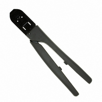
TOOL CRIMP MATE-N-LOK 14-20AWG
Manufacturer
Tyco Electronics
Series
Certi-Crimp™ II, Commercial MATE-N-LOK®r
Type
Crimpersr
Specifications of 91504-1
Tool Type
Hand Crimper
Features
Side Entry, Ratchet
Tools ,tyco Electronics / Amp
ROHS COMPLIANT
Product
Crimping, Stripping & Cutting Tools & Drills
Fits Cable/wire
20-14 AWG
Lead Free Status / RoHS Status
Not applicable / Not applicable
For Use With/related Products
Rectangular Contacts, 14-20 AWG
For Use With
170121-4 - CONN SOCKET M-N-L 14-20AWG TIN170121-1 - CONN SOCKET M-N-L 14-20AWG TINA25561 - CONN PIN 14-20AWG TIN CRIMPA25562 - CONN SOCKET 14-20AWG TIN CRIMPA25565 - CONN SOCKET 14-20AWG GOLD CRIMPA25568 - CONN PIN 16-18AWG TIN CRIMPA25570 - CONN SOCKET 16-18AWG TIN CRIMPA1435 - CONN SOCKET 14-20AWG GOLD CRIMPA1434 - CONN PIN 14-20AWG GOLD CRIMPA1421 - CONN SOCKET 14-20AWG TIN CRIMPA1420 - CONN PIN 14-20AWG TIN CRIMP
Lead Free Status / Rohs Status
Lead free / RoHS Compliant
Other names
A9908


2. DESCRIPTION
The FRONT of the tool, is marked with the tool part
number, wire size ranges, and crimp height
specifications.
The tool features a fixed die (crimper), a movable die
(anvil), a locator/insulation stop, and a CERTI–CRIMP
ratchet. Many tools feature an insulation adjustment
knob which is used to regulate the crimp height of the
contact insulation barrel during the crimping operation.
The locator/insulation stop positions the contact, and
limits the insertion distance of the stripped wire into the
contact. In use, the locator/insulation stop rests in the
locator slot of the contact (See Figures 1 and 2). The
CERTI–CRIMP ratchet assures full crimping of the
CERTI-CRIMP II Straight Action Hand Tools
D
2
D
NOTE:
Typical Socket
Contact
Figure 1
1
Typical
Pin Contact
PROPER USE GUIDELINES
Figure 2
contact. Once engaged, the ratchet will not release until
the dies have been fully closed.
3. CRIMPING PROCEDURE
Refer to the table at http://tooling.tycoelectronics.com to
ensure that the wire intended for use is compatible with
the wire size and insulation diameter specified in the
table. Strip the wire to the length indicated in the table.
Proceed as follows:
Insulation Adjustment Procedure
On many tools, the insulation barrel crimp height is
regulated by the insulation adjustment knob
(Figure 1). The insulation crimp should hold the
insulation firmly without cutting into the insulation.
To determine the proper insulation crimp setting, test
CAUTION
1. Hold the tool so that the FRONT side is facing you.
2. Ensure that the tool ratchet is released by
squeezing the tool handles and allowing them to open
FULLY.
3. Holding the contact by its mating portion and
looking straight into the crimp section, insert the
contact from the BACK of the tool into the appropriate
crimp chamber.
4. Position the contact between the crimpers so that
the locator/insulation stop enters the slot in the
contact. The wire barrel should butt against the
locator/insulation stop. Refer to Figures 1 and 2.
5. Holding the contact in this position, squeeze the
tool handles together until the insulation anvil starts
entry into the insulation crimper (usually two ratchet
clicks). Do NOT deform the insulation barrel or wire
barrel.
6. Insert a properly stripped wire through the locator
slot and into the wire barrel of the contact until the
insulation butts against the locator/insulation stop.
7. Holding wire in place, crimp contact to the wire by
squeezing the tool handles together until the ratchet
releases.
8. Allow tool handles to open FULLY and remove the
crimped contact from the tool.
Do NOT cut or nick the wire strands during wire
stripping.
Note:
408-8547
E