1490749-1 Tyco Electronics, 1490749-1 Datasheet

CRIMP TOOL HYDRAULIC

1490749-1

Manufacturer Part Number
1490749-1
Description
CRIMP TOOL HYDRAULIC
Manufacturer
Tyco Electronics
Series
Ampli-Bond™, Ampower™, Solistrand™, Terminyl™r
Datasheet

Specifications of 1490749-1

Tool Type
Handle, Frame - without Die Set
Features
Side Entry
For Use With
1752681-3 - INDENT U-DIE SOLIS FLAG 6-2AWG1752681-1 - INDENT U-DIE SOLS FLAG 1/0-4/01752680-8 - NEST U-DIE SOLISTRAND FLAG 8AWG1752680-7 - NEST U-DIE SOLISTRAND FLAG 6AWG1752680-6 - NEST U-DIE SOLISTRAND FLAG 4AWG1752680-5 - NEST U-DIE SOLISTRAND FLAG 2AWG1752680-4 - NEST U-DIE SOLISTRAND FLAG 1/01752680-3 - NEST U-DIE SOLISTRAND FLAG 2/01752680-2 - NEST U-DIE SOLISTRAND FLAG 3/01752680-1 - NEST U-DIE SOLISTRAND FLAG 4/01490700-1 - DIE ASSEMBLY TERMINYL 1/0 BLUE1490406-1 - DIE ASSEMBLY TERMINYL 2AWG RED1583098-1 - DIE ASSY AMPOWER 4/01583097-1 - DIE ASSY AMPOWER 3/01583096-1 - DIE ASSEMBLY AMPOWER 2/01583095-1 - DIE ASSEMBLY AMPOWER 1/01583094-1 - DIE ASSEMBLY AMPOWER #21583093-1 - DIE ASSEMBLY AMPOWER #41583092-1 - DIE ASSEMBLY AMPOWER #61490536-1 - DIE ASSEMBLY AMPLI-BOND #41490535-1 - DIE ASSEMBLY AMPLI-BOND #61490534-1 - DIE ASSEMBLY AMPLI-BOND #81490414-3 - INDENT U-DIE SOLISTRAN 1/0-4/01490414-2 - TOOL INDENTER U-DIE SOLIS #6-21490414-1 - INDENTER U-DIE SOLISTRAND #81490413-8 - TOOL NEST U-DIE SOLISTRAND 4/01490413-7 - NEST U-DIE SOLISTRAND 3/01490413-6 - NEST U-DIE SOLISTRAND 2/01490413-5 - NEST U-DIE SOLISTRAND 1/01490413-4 - NEST U-DIE SOLISTRAND #21490413-3 - NEST U-DIE SOLISTRAND #41490413-2 - TOOL NEST U-DIE SOLISTRAND #61490413-1 - NEST U-DIE SOLISTRAND #81490410-1 - DIE ASSEMBLY AMPLI-BOND #21490599-1 - DIE SET 4AWG1490597-1 - DIE SET 8AWG
For Use With/related Products
Splices and Terminals, 4/0-8 AWG
Lead Free Status / RoHS Status
na
Other names
Q3288910
PROPER USE GUIDELINES
1. INTRODUCTION
Hydraulic Hand Crimping Tool 1490749–1 (Figure 1)
is designed for crimping the terminals and splices in
Figure 2. Read these instructions thoroughly before
using the hand tool.
2. DESCRIPTION
The hand tool has a stationary lever and a movable
lever. These levers are compressed to pump
hydraulic fluid behind the ram, moving it forward and
thereby closing the dies. After the crimping is
NOTE
TERMINALS
units [with U.S. customary units in brackets].
Figures and illustrations are for identification only
and are not drawn to scale.
imensions in this instruction sheet are in metric
Figure 2
WIRE SIZE
(AWG)
Tool 1490749-1
ydraulic
and Crimping
INSTRUCTION
S EET
Figure 1
complete, the movable lever is turned to depress the
plunger. The moving die retracts to its original
position, completing the crimping cycle.
3. DIE INSERTION AND REMOVAL
Before inserting dies, refer to instruction sheet
packaged with dies for detailed instructions: insert or
remove dies, as necessary, by following procedures
given in the instruction sheet for the dies.
4. CRIMPING PROCEDURE
CAUTION
CAUTION
DANGER
1. Strip wires to dimensions specified on the
instructions packaged with dies (see Figure 2).
2. Insert the terminal or splice in stationary die
according to instruction sheet packaged with dies.
3. Pump movable lever until moving die grips
terminal or splice.
!
!
To avoid damage to the tooling, never operate
the tool with the dies removed. Failure to insert
the dies before operation can result in damage to
the C"-Head or the tool ram.
To avoid personal injury, be sure to exercise
caution while holding terminals, splices, or wire in
the crimping area.
o not deform wire barrel of terminal or splice.
www.tycoelectronics.com
408-8717
1

1490749-1 Summary of contents

Page 1

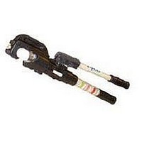
... These levers are compressed to pump hydraulic fluid behind the ram, moving it forward and thereby closing the dies. After the crimping is ydraulic and Crimping Tool 1490749-1 Figure 1 complete, the movable lever is turned to depress the plunger. The moving die retracts to its original position, completing the crimping cycle. ...

Page 2

... Select wire and terminal or splice for dies being used. 3. Place terminal or splice in dies according to instruction sheet packaged with dies. 4. Perform crimping procedure as described in Section 4, CRIMPING PROCEDURE, Steps 3 through 5. Do not release hydraulic pressure at this time. Tyco Electronics Corporation 08-8717 ev A ...

Page 3

... Weight: 7.8 kg (17.2 lb) Rev A or send a facsimile of your purchase order to 1–717–986–7605, or write to: CUSTOMER SERVICE (38–35) TYCO ELECTRONICS CORPORATION P.O. BOX 3608 HARRISBURG, PA 17105–3608 Crimping heads may also be returned for evaluation and repair. For tool repair service, contact a Tyco Electronics Representative at 1– ...