58517-2 Tyco Electronics, 58517-2 Datasheet - Page 2
58517-2
Manufacturer Part Number
58517-2
Description
DIE SET CST-100
Manufacturer
Tyco Electronics
Series
Pro-Crimper III, CST-100r
Type
Hand Tool Assemblyr
Specifications of 58517-2
Connector Type
Crimp Terminals
Crimp Handle
A9996-ND
Crimp Or Cable Size
22-26 AWG
Rohs Compliant
NA
Product
Crimping, Stripping & Cutting Tools & Drills
Lead Free Status / RoHS Status
Not applicable / Not applicable
Lead Free Status / RoHS Status
Not applicable / Not applicable
Other names
A19531


Rev E
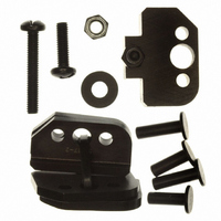
Die retaining pins and die retaining screws are used to
position and secure the dies in the tool frame. A
washer and nut is used on the lower die retaining
screw to hold the locator in place.
3. INSTALLATION AND REMOVAL OF DIE SET AND
LOCATOR ASSEMBLY
1. Open the tool handles and remove the two die
retaining screws from the tool jaws.
2. Place the wire anvil and insulation anvil in the
moving jaw so that their chamfered sides and
their marked surfaces face outward, when
mounted in the moving jaw of the tool frame.
3. Insert the two die retaining pins.
4. Insert the long die retaining screw through the
jaw and through both anvil dies, and tighten the
screw just enough to hold the dies in place. Do
not tighten the screw completely at this time.
5. Place the wire crimper and insulation crimper
in the stationary jaw so that their chamfered sides
and their marked surfaces face outward, when
mounted in the stationary jaw of the tool frame.
6. Insert the two die retaining pins.
7. Insert the short die retaining screw through the
jaw and through both crimper dies, and tighten
the screw just enough to hold the dies in place.
Do not tighten the screw completely at this time.
Chamfer
Offset
Wire
Crimper
Nut
Washer
Wire Anvil
Locator
(Figure 2)
Adjustment
Screw
Insulation
Crimper
Nut
Chamfer
Figure 2
Insulation
Anvil
4. CRIMPING PROCEDURE
8. Carefully close the tool handles, making sure
that the anvils and crimpers align properly.
Continue closing the tool handles until the ratchet
in the tool frame has engaged sufficiently to hold
the anvils and crimpers in place, then tighten both
die retaining screws.
9. Place the locator over the end of the long
screw, and position the locator against the side of
the tool jaw.
10. Place the washer and nut onto the end of the
long screw. Align the locator slot with the
crimping section and carefully tighten the nut.
11. To disassemble, close the tool handles until
the ratchet releases, remove the nut, the washer,
the locator, the two die retaining screws, and the
four die retaining pins, and slide the anvils and
crimpers out of the tool jaws.
NOTE
i
This tool is provided with a crimp adjustment
feature. Initially, the crimp height should be verified
as specified in Figure 4. Refer to Section 6, Crimp
Height Inspection, and Section 7, Crimp Height
Adjustment, to verify crimp height before using the
tool to crimp desired contacts and wire sizes.
Die Retaining Screws
Tool Frame
(or Bench
Machine, or
Ratched Hand
Tool)
408-4064
Die
Retaining
Pins
2 of 5