91901-1 Tyco Electronics, 91901-1 Datasheet - Page 3
91901-1
Manufacturer Part Number
91901-1
Description
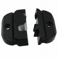
TOOL DIE ASSEMBLY
Manufacturer
Tyco Electronics
Series
Certi-Crimper™r
Type
Crimp Die Assemblyr
Specifications of 91901-1
Connector Type
BNC
Crimp Handle
A9996-ND
Crimp Or Cable Size
RG/U-55B
Product
Tool Component
For Use With
BNC RG 55B
Lead Free Status / RoHS Status
Not applicable / Not applicable
Lead Free Status / RoHS Status
na, Not applicable / Not applicable
Other names
Q1851413


6. MAINTENANCE AND INSPECTION
6.1. Maintenance
6.2. Inspection
Rev B
3. Observe the ratchet adjustment wheel. If a
tighter crimp is required, rotate the adjustment
wheel COUNTERCLOCKWISE to a
higher–numbered setting. If a looser crimp is
required, rotate the adjustment wheel
CLOCKWISE to a lower–numbered setting.
4. Replace the lockscrew.
5. Make a sample crimp and measure the crimp
height. If the crimp height is acceptable, secure the
lockscrew. If the dimension is unacceptable,
remove lockscrew and continue to adjust the
ratchet, and again measure a sample crimp.
1. Remove dust, moisture, and other contaminants
with a clean, soft brush, or a clean, soft, lint–free
cloth. Do NOT use any objects that could damage
the dies or tool.
2. Make sure that the proper die–retaining screws
are properly secured.
3. When the dies are not in use, store them in a
clean, dry area.
4. Store the tool with the tool handles closed to
prevent objects from becoming lodged within the
jaws.
1. Remove all lubrication and accumulated film
from the dies by immersing the dies in a suitable
commercial degreaser.
2. Make certain that all die–retaining screws and
die components are properly secured.
3. Inspect the crimping surfaces for flattened,
chipped, worn, or cracked areas. If damage is
evident, the dies must be replaced. Refer to
Section 7, REPLACEMENT.
Ratchet
Adjustment
Wheel
Lockscrew (Typ)
Screwdriver
Figure 4
SDE Crimping Die Assemblies
6.3. Measuring the Die Opening
The die assembly will perform correctly as long as:
(1) the product specified is correct for the application,
(2) the specific die assembly is used, (3) the die
assembly has been measured to ensure that the
openings are correct, and (4) the tool has been
adjusted correctly. Figure 5 provides information on
die opening sizes.
Die assembly 91901–1 will require a center contact
crimp height inspection using a micrometer with a
with a modified anvil as shown in Figure 6. Tyco
Electronics recommends use of the modified
micrometer (Crimp Height Comparator
RS–1019–5LP) which can be purchased from:
Proceed with center contact crimp height inspection
as follows:
7. REPLACEMENT
These crimping die assemblies are inspected before
shipment. It is recommended that the dies be
inspected immediately upon arrival at your facility to
ensure that the dies have not been damaged during
shipment.
Order replacements (or send for evaluation and
repair) through your local Tyco Electronics
Representative, or call 1–800–526–5142, or send a
facsimile of your purchase order to 1–717–986–7605,
or write to:
8. REVISION SUMMARY
Per EC: 0990–0121–04
Shearer Industrial Supply Co.
1. Select an appropriate center contact and cable.
2. Crimp a test center contact.
3. Using crimp height comparator, measure wire
barrel crimp height as shown in Figure 6. If the
crimp height conforms to that shown in the chart,
the tool is considered dimensionally correct. If not,
return the tool to Tyco Electronics for evaluation
and repair (refer to Section 7, REPLACEMENT).
CUSTOMER SERVICE (038–035)
TYCO ELECTRONICS CORPORATION
PO BOX 3608
HARRISBURG PA 17105–3608
S Updated document to corporate requirements
S Changed artwork and dimensions in table for
91901–1 in Figure 5
717–767–7575
or
610–691–3205
VALCO
408–8579
3 of 4