1583696-1 Tyco Electronics, 1583696-1 Datasheet - Page 2
1583696-1
Manufacturer Part Number
1583696-1
Description
DIE SET MMCX USE WITH A9996-ND
Manufacturer
Tyco Electronics
Series
Pro-Crimper™ IIIr
Datasheet
1.1583696-1.pdf
(3 pages)
Specifications of 1583696-1
Connector Type
MMCX, MCX
Crimp Handle
A9996-ND
Product
Tool Component
Lead Free Status / RoHS Status
Not applicable / Not applicable
Crimp Or Cable Size
-
Lead Free Status / Rohs Status
Lead free / RoHS Compliant
Other names
A30731


4. CRIMPING PROCEDURE
Before proceeding with crimping, determine the
proper tool and setting to provide the center
conductor crimp. Follow the manufacturer’s
recommended procedure.
2 of 3
3. Thread, but do not tighten, the die retaining
screws into the holes.
4. Carefully close the tool handles, making sure
that the dies align properly.
5. Tighten the die retaining screws with the
appropriate hex wrench.
NOTE
1. Make sure that the connector ferrule has been
placed onto the cable, and that the cable braided
shield is flared away from the cable.
2. Crimp the center contact by sliding it onto the
stripped center conductor of the coaxial cable until
it is butted against the dielectric, placing the center
contact in the smallest crimping chamber of the
anvil die, and closing the tool handles until the
ratchet releases.
3. Insert the crimped center contact into the
connector body until the cable dielectric butts
against the dielectric inside of the connector body
or until the center contact is securely positioned
within the connector. Make sure that the braided
shield is over the support sleeve of the connector
body, and that no strands from the shield enter the
connector body.
4. Slide the ferrule over the braided shield and
onto the connector until the ferrule butts against
the shoulder on the connector body.
5. Place the ferrule on the appropriate crimping
chamber of the anvil die so that the shoulder on
the connector body is close to the edge of the die.
NOTE
6. While holding the assembly together, begin to
close the tool handles. Keep holding the assembly
until the dies have closed enough to clamp the
assembly in place.
7. Carefully close the tool handles until the ratchet
releases.
This tool will not provide a crimp conforming to
military requirements, nor can it be used on
mil–type connectors.
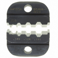
To determine the appropriate crimping chamber,
observe the markings above the crimping
chambers, and refer to the instructions packaged
with the connector.
Hex Crimping Die Assembly 1583696–1
5. MAINTENANCE AND INSPECTION
5.1. Daily Maintenance
5.2. Visual Inspection
5.3. Measuring Die Opening
The die assembly will perform correctly as long as:
(1) the product specified is correct for the application,
(2) the specific die assembly is used, (3) the die
assembly has been measured to ensure that the
openings are correct, and (4) the die assembly
bottoms.
Figure 3 provides information on die opening sizes.
For specific applications where wire stiffness,
material, or insulation may give different than
standard performance, it may be necessary to
measure the crimped ferrule, rather than to verify the
size of the die opening. This inspection requires the
use of a cone or modified micrometer (Crimp Height
Comparator RS–1019–5LP), which is available from:
CAUTION
Shearer Industrial Supply Co.
8. Allow the tool handles to open fully and remove
the crimped connector from the dies.
1. Remove dust, moisture, and other contaminants
with a clean, soft brush, or a clean, soft, lint–free
cloth. Do NOT use any objects that could damage
the dies or tool.
2. Make sure that the proper die retaining screws
are properly secured.
3. When the dies are not in use, store them in a
clean, dry area. When the tool is not in use, store it
with the handles closed to prevent objects from
becoming lodged within the jaws.
1. Remove all lubrication and accumulated film
from the dies by immersing the dies in a suitable
commercial degreaser.
2. Make certain that all die retaining screws and
die components are properly secured.
3. Inspect the crimping surfaces for flattened,
chipped, worn, or cracked areas. If damage is
evident, the dies must be replaced. Refer to
Section 6, REPLACEMENT.
717–767–7575
Damaged product must not be used. If damaged
product is evident, it must be cut from the wire
and replaced with a new one. Contacts or
connectors must not be reterminated.
or
610–691–3205
VALCO
408–8853
Rev O