59993-1 Tyco Electronics, 59993-1 Datasheet

TOOL DIE RG-174/316/188/179/187

59993-1

Manufacturer Part Number
59993-1
Description
TOOL DIE RG-174/316/188/179/187
Manufacturer
Tyco Electronics
Datasheet

Specifications of 59993-1

Connector Type
Coax Connectors
Crimp Handle
A28006-ND
Crimp Or Cable Size
RG/U-174, 179, 187, 188, 316
For Use With
228596-2 - CONN SOCKET STR SIZE 8 RG179,187228618-2 - CONN PIN STRAIGHT 30AU COAXIAL228618-1 - CONN PIN COAXIAL STRAIGHT GOLD
Lead Free Status / RoHS Status
Not applicable / Not applicable
Other names
A34783
1. INTRODUCTION
AMP* Crimping Die Assembly 59993–1 is used to
crimp Size 8 coaxial RF 50–ohm and non–impedance
matched straight pin and socket contacts onto various
types and sizes of coaxial cable. The die assembly is
used with Hand Crimping Tool 69710–1 or 69710–2,
or 626 Pneumatic Tooling Assembly 189721–2 or
189722–2 fitted with C–Head Pneumatic Adapter
318161–1. The die assembly can also be used with
Pneumatic Tool 69365–8.
For cable–to–contact selection, refer to Catalog
82074. Refer to 408–2095 for instructions concerning
operation of the hand tool and 409–5862 for 626
pneumatic tooling assembly.
Reasons for reissue of this instruction sheet are
provided in Section 6, REVISION SUMMARY.
2. DESCRIPTION
The die assembly consists of a indenter (stationary
die) and anvil (movable die), both of which contain
two crimping chambers. The small crimping chamber
crimps the center contact, and the large crimping
chamber crimps the ferrule. Each die is held in the
tooling by a single screw.
Center Contact
Crimping Chamber
E
All International Rights Reserved.
*Trademark
1999 AMP Incorporated, Harrisburg, PA.
NOTE
Ferrule Crimping
Chamber
Stationary Die
(Indenter)
Screw
Dimensions in this instruction sheet are in
millimeters [with inches in brackets]. Figures are
not drawn to scale.
(Figure 1)
Figure 1
Crimping Die Assembly 59993–1
This controlled document is subject to change.
For latest revision call the AMP FAX* number.
Movable Die
(Anvil)
3. CRIMPING PROCEDURE
Install dies according to the instructions packaged
with the tooling. Then proceed as follows:
3.1. Center Contact
Indenter Entering
Contact Port Hole
NOTE
1. Prepare and assemble the center contact
according to 408–6755.
2. Position contact assembly in the center contact
crimping chamber so that the indenter aligns with
the port hole of the contact. See Figure 2.
3. Close dies (according to the instructions
packaged with the tool) onto contact until the
indenter starts to enter the contact port hole. Align
the other port hole over the anvil.
NOTE
Center Contact
Crimping Chamber
4. Holding cable and contact in position, actuate
tool through a complete cycle to crimp the contact.
5. Remove contact assembly from tool.
TOOLING ASSISTANCE CENTER 1–800–722–1111
AMP FAX/PRODUCT INFO 1–800–522–6752
The tools are designed to accept interchangeable
crimping dies and are used to crimp a variety of
product. Make certain that the selected contact
and cable are compatible with the die assembly.
When using Pneumatic Tool 69365–8, pull the
handle (located on take–up attachment) forward
to close dies on contact.
Anvil Aligned with
Contact Port Hole
Figure 2
Instruction Sheet
408–6775
14 SEP 99 Rev A
LOC B
1 of 4

59993-1 Summary of contents

Page 1

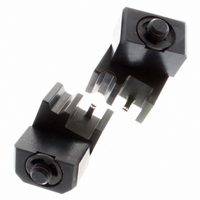
... Center Contact Crimping Chamber Figure 1 1. INTRODUCTION AMP* Crimping Die Assembly 59993–1 is used to crimp Size 8 coaxial RF 50–ohm and non–impedance matched straight pin and socket contacts onto various types and sizes of coaxial cable. The die assembly is used with Hand Crimping Tool 69710–1 or 69710–2, or 626 Pneumatic Tooling Assembly 189721– ...

Page 2

... Crimping Die Assembly 59993–1 3.2. Ferrule 1. Slide the ferrule over the cable braid and contact support sleeve until the ferrule bottoms against the contact body. 2. Insert contact body through the ferrule crimping chamber from the FRONT of the tool. Make sure that the shoulder on the ferrule is against the edge of the ferrule crimping chamber ...

Page 3

... Crimping Die Assembly 59993–1 Suggested Plug Gage Design GO Diameter W Center Contact Die Closure Configuration Die Closure Configuration GAGE ELEMENT DIAMETER CRIMPING CRIMPING CHAMBER GO NO–GO Center 0.940–0.947 1.013–1.016 Contact [.0370–.0373] [.0399–.0400] 3.200–3.208 3.325–3.327 Ferrule [.1260– ...

Page 4

... Crimping Die Assembly 59993–1 15.88 [.625 Weight: 850 kg [3 oz] (Approx) ITEM PART NUMBER 1 312789–1 2 312790–1 3 3–306131–4 4 2–59674–6 5 1–21046–3 6 3–59675– 23.77 [.936 REPLACEMENT PARTS DESCRIPTION DIE, Stationary (Indenter) DIE, Movable (Anvil) ...