90390-3 Tyco Electronics, 90390-3 Datasheet - Page 4
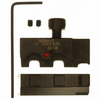
90390-3
Manufacturer Part Number
90390-3
Description
DIE SET ULTRA-FASTONS 22-18 AWG
Manufacturer
Tyco Electronics
Series
Pro-Crimper™ III, Faston™r
Type
Crimpersr
Specifications of 90390-3
Connector Type
Terminals and Splices
Crimp Handle
A28005-ND
Crimp Or Cable Size
18-22 AWG
Receptacles And Tabs ,tyco Electronics / Amp
ROHS COMPLIANT
Fits Cable/wire
22-18 AWG
Product
Tool Component
Lead Free Status / RoHS Status
Not applicable / Not applicable
For Use With
Platform Hand Tool Frame 58078-3
Lead Free Status / RoHS Status
Not applicable / Not applicable
Other names
90390-3
A28007
A28007


5.2. Periodic Inspection
Regular inspection should be performed by quality
control personnel. A record of scheduled inspections
should remain with the tool and/or be supplied to the
supervisory personnel responsible for the tool.
Though recommendations call for at least one
inspection a month, the inspection frequency should
be based on the amount of use, ambient working
conditions, operator training and skill, and established
company standards. These visual inspections should
be performed in the following sequence:
5.3. Gaging the Crimping Chamber
This inspection requires the use of a plug gage
conforming to the diameters in Figure 5. Tyco
Electronics does not manufacture or market these
gages.
Proceed as follows:
4
of 5
1. Remove all lubrication and accumulated film by
immersing the dies in a suitable degreaser that will
not affect paint or plastic material.
2. Make sure all die holding screws and die
components are in place. Refer toe parts listed in
Figure 6 if replacements are necessary.
3. Check all bearing surfaces. Remove and
replace worn components.
4. Inspect the crimp area for flattened, chipped,
cracked, worn or broken areas. If damage is
evident, the dies must be repaired before returning
them to service. Refer to Section 6, REPAIR.
1. Mate the dies until it is evident that they have
bottomed. Hold the dies in this position with a
pressure of approximately 69 kPa [10 psi].
2. Align the GO element with the wire barrel
crimping chamber. Push element straight into the
crimping chamber without using force. The GO
element must pass completely through the
crimping chamber as shown in Figure 5.
3. Align the NO–GO element and try to insert it
straight into the same crimping chamber. The
NO–GO element may start entry but must not pass
completely through, as shown in Figure 5.
Crimping Die Assemblies 90390-3 and 90391-3
If the crimping chamber conforms to the gage
inspection, the dies are considered dimensionally
correct and should be lubricated with a THIN coat of
SAE 20 motor oil. If not, the dies must be repaired
before returning them to service.
For additional information concerning the use of a
plug gage, refer to Instruction Sheet 408–7424.
É
É É
É
É
Platform
90390-3
90391-3
Number
GO Element Must Pass
Through Crimping Chamber
GO
Dia
Die
Die
Suggested Plug Gage Design
NO-GO Element Must Not Pass
Through Crimping Chamber
Terminal
Number
Number
520081
520084
520273
520182
520194
520275
520184
520264
520103
520129
520335
520337
350616
520125
520151
350820
520117
520107
520141
520133
520339
(LP)
Figure 5
1.57 [.062]
1.83 [.072]
GO
Element Diameter
É
É É
É
É
1.73 [.068]
1.98 [.078]
NO-GO
NO-GO
408-9279
Dia
Rev
B