318450-2 Tyco Electronics, 318450-2 Datasheet - Page 3
318450-2
Manufacturer Part Number
318450-2
Description
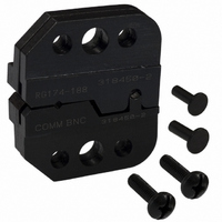
PROCRIMP DIE ASSY BNC TNC
Manufacturer
Tyco Electronics
Type
Dier
Specifications of 318450-2
Connector Type
BNC, TNC
Crimp Handle
Tyco/AMP 318450-1
Crimp Or Cable Size
RG/U-161, 174, 179, 187, 188, 316
Crimp Tool
Hand Crimper III
Product
Tool Component
Description/function
O Crimp Commercial
Features
Die for Pro-Crimper
For Use With
SDE Dies
Lead Free Status / RoHS Status
Not applicable / Not applicable
Lead Free Status / RoHS Status
na, Not applicable / Not applicable
Other names
A24780


4.2. Ferrule
Rev
Center Contact Crimp
Center Contact
Flange Against
Edge of Die
Ferrule Crimp
PRO-CRIMPER III Hand Crimping Tool Assembly 318450-1
3. Allow the handles to open fully, and remove the
crimped center contact from the die assembly.
1. Flare the cable braid and insert the crimped
center contact into the connector body until the
cable dielectric is against the dielectric inside the
connector body. The flared braid will then fit over
the support sleeve of the connector body.
2. Slide the ferrule forward over the braid until the
ferrule is against the connector body.
B
Anvil Die
Ferrule
Anvil Die
Stripped
Cable
(Figure 4)
Figure 3
Tyco Electronics Corporation
Figure 4
5. INSPECTION
5.1. Visual Inspection
The crimping dies should be inspected on a regular
basis to ensure that they have not become worn or
damaged. Inspect the crimping chambers for
flattened, chipped, worn, or broken areas. If damage
or abnormal wear is evident, the tool must be
replaced. See Section 8, DIE REPLACEMENT.
5.2. Gaging the Crimping Chamber
This inspection requires the use of a plug gage
conforming to the diameters in Figure 5. Tyco
Electronics does not manufacture or market these
gages. To gage the crimping chamber, proceed as
follows:
CAUTION
3. Place the ferrule in the ferrule crimping chamber
on the anvil die so that the shoulder of the
connector body is against the edge of the die.
4. Holding the assembly in place, close the tool
handles until the ratchet releases.
5. Allow the handles to open fully, and remove the
crimped assembly from the die assembly.
1. Close the jaws until the dies have bottomed,
then HOLD the frame handles in this position. Do
NOT force the dies beyond initial contact.
!
Cross-Sectional
View
Connector Shoulder
Against Edge of Die
Damaged contacts must not be used. If a contact
is damaged, it must be replaced with a new one.
Anvil Die
408-4218
3
of 5