318451-2 Tyco Electronics, 318451-2 Datasheet
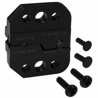
DIE SET

318451-2

Manufacturer Part Number
318451-2
Description
DIE SET
Manufacturer
Tyco Electronics
Series
Pro-Crimper™ IIIr
Type
Crimp Toolr
Datasheets

Specifications of 318451-2

Connector Type
Coax Connectors
Crimp Handle
Tyco/AMP 318451-1
Crimp Or Cable Size
RG/U-79, 161, 187
Features
"O" / Commercial
Crimp Application
Coaxial
Product
Crimping, Stripping & Cutting Tools & Drills
For Use With
75 Ohm BNC RF/Coaxial Connectors
Lead Free Status / RoHS Status
Not applicable / Not applicable
Lead Free Status / RoHS Status
na, Not applicable / Not applicable
Other names
318451-2
A24630
PROPER USE GUIDELINES
1. INTRODUCTION
PRO–CRIMPER III Hand Crimping Tool Assembly
318451–1 consists of Die Assembly 318451–2 and
PRO–CRIMPER III Hand Crimping Tool Frame
354940–1. The hand tool assembly is used to crimp
75–Ohm RF Series BNC Commercial Plug Connector
221185–8 and Bulkhead Jack Connector 221221–5
onto various sizes of RG/U cable.
For connector assembly and cable stripping
procedures, refer to instruction sheet 408–9088 for
the plug connectors and 408–9089 for the jack
connectors. Read these instructions thoroughly
before using the hand tool assembly. This document
supersedes Instruction Sheet 408–9282.
E
NOTE
i
Dimensions on this sheet are in millimeters
[with inches in brackets]. Figures are for
reference only and are not drawn to scal
PRO-CRIMPER* III Hand Crimping
Tool Assembly 318451-1 with
Die Assembly 318451-2
Figure 1
Reasons for reissue of this instruction sheet are
provided in Section 9, REVISION SUMMARY.
2. DESCRIPTION
The hand tool assembly features a tool frame with a
stationary jaw and handle, a moving jaw, a moving
handle, and an adjustable ratchet that ensures full
connector crimping.
The tool frame holds a die assembly with two
crimping chambers. The die assembly features a wire
anvil, an insulation anvil, a wire indenter, and an
insulation indenter. Die retaining pins and die retaining
screws are used to position and secure the dies in the
tool frame.
www.tycoelectronics.com
408-4217
1

318451-2 Summary of contents

Page 1

... Figures are for i reference only and are not drawn to scal E PRO-CRIMPER* III Hand Crimping Tool Assembly 318451-1 with Die Assembly 318451-2 Figure 1 Reasons for reissue of this instruction sheet are provided in Section 9, REVISION SUMMARY. 2. DESCRIPTION The hand tool assembly features a tool frame with a ...

Page 2

... PRO-CRIMPER III Hand Crimping Tool Assembly 318451-1 Insulation Wire Indenter Indenter Wire Anvil Ferrule Crimping Chamber Insulation Anvil Center Contact Crimping Chamber 3. INSTALLATION AND REMOVAL OF DIE ASSEMBLY (Figure 2) 1. Open the tool handles and remove the two die retaining screws from the tool jaws. ...

Page 3

... PRO-CRIMPER III Hand Crimping Tool Assembly 318451-1 Center Contact Crimp Center Contact Flange Against Edge of Die Anvil Die Stripped Cable Figure 3 4.2. Ferrule (Figure 4) 1. Flare the cable braid and insert the crimped center contact into the connector body until the cable dielectric is against the dielectric inside the connector body ...

Page 4

... Figure 5. If the crimp height conforms to that shown, the die assembly is considered dimensionally correct. If not, return the dies to Tyco Electronics for evaluation and repair (refer to Section 8, DIE REPLACEMENT). This inspection requires the use of a plug gage conforming to the dimensions in Figure 6. Tyco Electronics does not manufacture or market these gages ...

Page 5

... Order replaceable parts through your Tyco Electronics Representative, or call 1–800–526–5142, or send a facsimile of your purchase order to 1–717–986–7605, or write to: CUSTOMER SERVICE (38–35) TYCO ELECTRONICS CORPORATION PO BOX 3608 HARRISBURG PA 17105–3608 For customer repair service, contact a Tyco Electronics Representative at 1–800–526–5136. ...