PROPER USE GUIDELINES
Cumulative Trauma Disorders can result from the prolonged use of manually powered hand tools. Hand tools are intended for occasional use and low volume
applications. A wide selection of powered application equipment for extended- - use, production operations is available.
1. INTRODUCTION
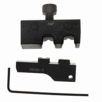
This instruction sheet covers application and
maintenance procedures for Crimping Die Assemblies
58079--3 and 58080--3. See Figure 1. Each die
assembly is used with Hand Crimping Tool Frame
58078--3, which will crimp the Ultra--Fast Plus Fully
Insulated FASTON* Terminals listed in Figure 2.
Refer to Instruction Sheet 408--6976 (supplied with
tool frame) for specific tooling information. Product
part number information is available in Catalog 82004.
Reasons for reissue are provided in Section 7,
REVISION SUMMARY.
2. DESCRIPTION
Each die assembly consists of an upper die (crimper)
and a lower die (anvil), a die retention screw (on
upper die), and a hex wrench for securing the socket
head setscrew to the lower die and onto the hand tool
E2011 Tyco Electronics Corporation, a TE Connectivity Ltd. Company
All Rights Reserved
*Trademark
TE Connectivity, TE connectivity (logo), and TE (logo) are trademarks. Other logos, product and/or Company names may be trademarks of their respective owners.
Upper Die
(Crimper)
Crimping
Chamber
Wire Size
Range
Markings
NOTE
i
Dimensions are in millimeters [with inch
equivalents in brackets]. Figures are for
identification only and are not drawn to scale.
Wire Size Range
Markings
Figure 1
Crimping Die Assemblies
58079- 3 and 58080- 3
Die Retention
Screw
Lower Die
(Anvil)
TOOLING ASSISTANCE CENTER 1--800--722--1111
PRODUCT INFORMATION 1--800--522--6752
Color
Dot
Code
platform. When mated, the dies form two crimping
chambers, each marked with the wire size range.
The die assemblies are identified by the part number,
color dot code, and applicable wire range markings.
Refer to Figure 2. The color dot code on the die
assembly must match the color--coded terminal.
3. DIE ASSEMBLY INSTALLATION
3.1. Installing Lower Die
3.2. Installing Upper Die
(AWG)
22--18
16--14
SIZE
NOTE
1. Close tool frame handles until ratchet releases,
then allow handles to open FULLY.
2. Slide lower die onto lower jaw platform of tool
frame. Make sure that the hole on the side of the
lower die aligns with the socket head setscrew on
the platform. See Figure 3.
3. Using hex wrench, turn socket head setscrew
CLOCKWISE until snug. Do NOT overtighten.
1. Remove die retention screw from upper die.
2. Slide upper die onto upper jaw platform of tool
frame. Make sure the color dot code on upper die
is on the same side as the color dot code on lower
die. See Figure 3.
i
WIRE
INSUL
(MAX)
[.135]
[.135]
[.160]
[.160]
DIA.
3 43
3.43
4 06
4.06
If lower die will not position properly, use hex
wrench provided with die assembly to turn
socket head setscrew either in or out until lower
die positions properly.
SERIES
ULTRA- - FAST PLUS
.187
.250
.187
.250
This controlled document is subject to change.
For latest revision and Regional Customer Service,
visit our website at www.te.com
187
187
TERMINALS
Figure 2
2--520409--2
2--520411--2
2--520407--2
3--520410--2
3--520412--2
3--520408--2
PART NO.
COLOR
CODE
DOT
Blue
Instruction Sheet
Red
408- - 9278
25 APR 11
DIE ASSEMBLY
PART NO.
58079--3
58080--3
Rev B
1 of 4
LOC B