318845-1 Tyco Electronics, 318845-1 Datasheet
318845-1
Manufacturer Part Number
318845-1
Description
EXTRACTION TOOL ASSY
Manufacturer
Tyco Electronics
Series
MATE-N-LOK®r
Type
Extraction Toolr
Specifications of 318845-1
Tool Type
Extraction Tool
Tool Body Material
Plastic
Body Material
Metal Tip, Plastic Handle
Features
Spring-Loaded Tip
Integral Plunger
Interlock Lever
Product
Insertion / Extraction Tool
For Use With
A25752CT - CONN SOCKET 10-14AWG TIN CRIMPA25751CT - CONN PIN 10-14AWG TIN CRIMPA25461CT - CONN SOCKET 10-14AWG TIN CRIMPA25460CT - CONN PIN 10-14AWG TIN CRIMPA25456CT - CONN PIN 14-20AWG TIN CRIMPA25455CT - CONN SOCKET 14-20AWG TIN CRIMPA25454CT - CONN PIN 14-20AWG TIN CRIMPA25752 - CONN SOCKET 10-14AWG TIN CRIMPA25751 - CONN PIN 10-14AWG TIN CRIMPA25454 - CONN PIN 14-20AWG TIN CRIMPA25455 - CONN SOCKET 14-20AWG TIN CRIMP770484-1 - CONN PIN 10-14AWG TIN CRIMP TERMA25456TR - CONN PIN 14-20AWG TIN CRIMPA25457TR - CONN SOCKET 14-20AWG TIN CRIMPA25460 - CONN PIN 10-14AWG TIN CRIMPA25461 - CONN SOCKET 10-14AWG TIN CRIMPA25751TR - CONN PIN 10-14AWG TIN CRIMPA25752TR - CONN SOCKET 10-14AWG TIN CRIMPA25454TR - CONN PIN 14-20AWG TIN CRIMPA25455TR - CONN SOCKET 14-20AWG TIN CRIMPA25460TR - CONN PIN 10-14AWG TIN CRIMPA25461TR - CONN SOCKET 10-14AWG TIN CRIMP
Lead Free Status / RoHS Status
Not applicable / Not applicable
For Use With/related Products
Rectangular Connector Contacts
Lead Free Status / Rohs Status
Lead free / RoHS Compliant
Other names
A25474
1. INTRODUCTION
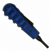
Extraction Tool 318845-1, shown in Figure 1, is
designed to remove .140 contacts, listed in Figure 2,
from MATE-N-LOK* Connectors. Read these
instructions thoroughly before attempting to remove
any contacts.
Reasons for reissue of this document are provided in
Section 5, REVISION SUMMARY.
2. DESCRIPTION (Figure 1)
The extraction tool consists of a spring-loaded metal
tip with an integral plunger mounted to a plastic handle
with an interlock lever. When the interlock lever is
depressed, the plunger is held until the contact locking
lances are depressed by the tip. After the lever is
released, the plunger is released, permitting the
contact to be pushed out the rear of the housing.
3. EXTRACTION PROCEDURE (Figure 3)
© 2011 Tyco Electronics Corporation, a TE Connectivity Ltd. Company
All Rights Reserved
*Trademark
TE Connectivity, TE connectivity (logo), and TE (logo) are trademarks. Other logos, product and/or Company names may be trademarks of their respective owners.
1. Determine the contact to be removed and grasp
the wire attached to that contact.
2. Move the contact forward as far as possible by
pushing the wire toward the housing.
Plastic
Handle
350201-[ ]
770484-[ ]
NOTE
61627-[ ]
i
PIN
STRIP
If pushing the wire by hand is difficult, use Insertion
Tool 91002-1.
350200-[ ]
SOCKET
61626-[ ]
- -
Interlock
Lever
Figure 1
Figure 2
350389-[ ]
350391-[ ]
PIN
Extraction Tool 318845-1
- -
LOOSE PIECE
Spring-Loaded
Metal Tip
TOOLING ASSISTANCE CENTER 1-800-722-1111
PRODUCT INFORMATION 1-800-522-6752
350388-[ ]
350390-[ ]
SOCKET
- -
4. TOOL MAINTENANCE
It is recommended that the tool be inspected when you
receive it and at regularly scheduled intervals. The tool
is not repairable and should be replaced when it is
worn or damaged. Store the extraction tool in a clean,
dry place and clean the extraction tool with a soft, lint-
free cloth.
Additional tools can be purchased from:
5. REVISION SUMMARY
Since the previous version of this document, the
following changes were made:
3. Depress the extraction tool interlock lever and
insert the tip of the tool into the contact cavity in the
mating face of the housing. Make sure that the tip is
completely bottomed in the cavity.
4. While holding the extraction tool in position and
pulling back on the wire, release the interlock lever
and push the tool handle forward. The wire and
contact should pull out of the housing.
•
CUSTOMER SERVICE (038-035)
TYCO ELECTRONICS CORPORATION
PO BOX 3608
HARRISBURG PA 17105-3608
Extraction
Tool
NOTE
Updated document to corporate requirements.
i
Push Wire Toward Housing
Before Engaging Tool Tip
Before using the contact again, reset the locking
lances to their original positions. To obtain the
correct setting dimensions for the locking lances,
consult the Customer Drawing covering the specific
contact, or contact TE Connectivity engineering.
This controlled document is subject to change.
For latest revision and Regional Customer Service,
visit our website at www.te.com
Figure 3
Mating Face of
Housing (Ref)
Instruction Sheet
408-4378
09 MAY 11 Rev A
1 of 1
LOC B