3442-41N 3M, 3442-41N Datasheet - Page 3
3442-41N
Manufacturer Part Number
3442-41N
Description
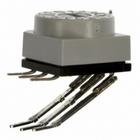
PLATEN D-SUB 25&37POS PLUGS
Manufacturer
3M
Datasheet
1.3442-41N.pdf
(4 pages)
Specifications of 3442-41N
Lead Free Status / RoHS Status
Not applicable / Not applicable
Other names
0-00-54007-83918-7
00054007839187
05400783918
3442-41N
344241N
3M9431
5400783918
54007839187
80-6105-7558-3
80-610575583
80610575583
00054007839187
05400783918
3442-41N
344241N
3M9431
5400783918
54007839187
80-6105-7558-3
80-610575583
80610575583


Preassembled Connector Assembly Procedure
Set-up
1. Adjust the end block according to the flange style and connector size.
Thru-hole style: Rotate the end block so that the locating pin is facing the inside of the locator plate.
The pin has to be removed so that the end block can be rotated. Then reassemble the pin. The pin is
used to guide the platen during harness assembly.
Floating bushing and threaded insert style:
Rotate the end block so that the locating pin is facing the outside of the locator plate.
2. Install the cable stop insert 3664-B.
3. Install the cable guide on the mounting stud. Refer to the last page for the appropriate guide.
4. Place the locator plate on the press and affix it using the locking screw provided.
5. Place the platen on the assembly press. Refer to the last page for the appropriate platen.
Assembly
1. Cut required cable length using one of the 3M cutting tools.
2. Remove the connector from the packing strip.
3. Slide the connector onto the guiding groove and into the end block.
4. Slide the cable under the cable guide. If the cable should not enter into the connector smoothly, check the
5. Complete the assembly by bringing the press handle to the full downward position.
6. Raise the press handle and cable guide, then remove completed assembly.
7
Two-Piece Connector Assembly Procedure
Set-up
1. Follow steps 1, 4 and 5 of the preassembled set-up instructions.
Assembly
1. Grasp 3M
2. Press cable ribs into cover alignment grooves.
3. Visually inspect to insure that the cable is properly aligned and oriented into cover grooves.
4. Engage cable/cover subassembly with connector body. Place subassembly in the locator plate with the
5. Complete the assembly by bringing the press handle to the full downward position.
6. Raise the press handle and remove the completed assembly.
7. Visually inspect to insure that:
flatness of the cable.
Visually inspect to insure that:
a. The cover is fully seated. If not, check the shut height setting.
b. The cable is correctly aligned in the cover. If not, check end guide adjustment.
away from strip leaving the adhesive with a smooth clean edge.
connector body facing up.
a. The cover is fully seated. If not, check the shut height setting.
b. The cable is correctly aligned in the cover. If not, check end guide adjustment.
™
Delta Cover Strip between thumb and forefinger. While holding the adjacent cover, pull laterally
F
C
3
B
E
A
78-8133-3685-2-A
D