10961 3M, 10961 Datasheet - Page 2
10961
Manufacturer Part Number
10961
Description
MDR CUTTING UNIT
Manufacturer
3M
Series
MDRr
Type
Cutting Unitr
Datasheet
1.10960-2000.pdf
(6 pages)
Specifications of 10961
Tool Type
Cutting Unit
Description/function
Cutting unit for 3M Handpress 10960-2000
Rohs Compliant
YES
Lead Free Status / RoHS Status
Vendor undefined / Vendor undefined
Other names
90169008567
JE150172870
JE150172870
Available stocks
Company
Part Number
Manufacturer
Quantity
Price


6.
Figure 3. Press leaned back
Figure 4. 10960-2000 Hand Press
2
B.
Side bar
knob &
platen
E.
Thumbscrew
Locate cutting unit stop brackets and thumbscrew (D & E
of Fig. 4). Depending on size of assembly choose
stop bracket accordingly.
(Black for 14-50 position and Silver for 68-100 position.)
Stop brackets are installed using the thumbscrew
(A & B of Fig. 2).
D.
Stop brackets
F.
Gauge block
A.
Height
adjustment
knob
C.
Shuttle
block
3
4
7.
8.
9.
10. Locate the shuttle block (C of Fig. 4) and install fixture
11. Locate the gauge block (F of Fig. 4). Height adjustment
12. Push shuttle, with fixture unit and gauge block, away
13. Pull the press handle down, toward the operator, until
14. Adjust the silver knob at the top of the press (A of Fig. 4)
15. Height adjustment should be checked periodically.
Fixture Unit Adjustment
Once the size of the connector to be assembled has been
determined the 10962 Fixture Unit requires some adjustments.
1.
2.
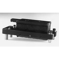
Figure 5. 10961 Cutting Unit
B
Push platen back into place using the side bar.
After installing the stop bracket, position the armature
of the press back in an upright position. Tighten the
thumbscrew (C of Fig. 2) to hold it in place.
Located at the back of the press is a silver, dowel shaped
shuttle stop (D of Fig. 2). Set shuttle stop for appropriate
connector pin count.
unit (Fig. 14) on the guide pins. Push the release buttons
on the front of the fixture unit to open the grooved plates.
can be accomplished by placing the gauge block, narrow
side down, in the fixture unit between the two grooved
plates. Close plates manually by squeezing
them together.
from the operator to the rear of the press until it stops.
the platen contacts the gauge block.
DO NOT FORCE HANDLE.
by hand until the platen lightly contacts the gauge block.
Lift press handle up and adjust the silver knob
approximately another one-half turn tighter. Pull handle
down again. It should lightly lock in place when fully
depressed. The platen should apply enough pressure
on the gauge block and shuttle to prevent them from
moving when trying to slide them out.
Select the correct connector stop (14, 20, 26, 36, 40, 50,
68, 80 or 100 position; B of Fig. 14) for your application.
Locate the yolk shaped cover plate (A of Fig. 14) and
thumbscrew at the top of the fixture unit. Remove
and set aside. Close fixture unit grooved plates by
manually squeezing them together.
A
5