MAL215957331E3 Vishay, MAL215957331E3 Datasheet - Page 2
MAL215957331E3
Manufacturer Part Number
MAL215957331E3
Description
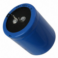
CAP 330UF 450V ELECT SNAP-IN
Manufacturer
Vishay
Series
159 PUL-SIr
Datasheet
1.MAL215966331E3.pdf
(8 pages)
Specifications of MAL215957331E3
Capacitance
330µF
Voltage Rating
450V
Tolerance
±20%
Lifetime @ Temp.
5000 Hrs @ 105°C
Operating Temperature
-25°C ~ 105°C
Features
General Purpose
Ripple Current
1.49A
Esr (equivalent Series Resistance)
300.0 mOhm
Impedance
390 mOhm
Mounting Type
Through Hole
Package / Case
Radial, Can - Snap-In
Size / Dimension
1.378" Dia (35.00mm)
Height
1.575" (40.00mm)
Lead Spacing
0.394" (10.00mm)
Lead Free Status / RoHS Status
Lead free / RoHS Compliant
Surface Mount Land Size
-
Other names
4362PHBK


TWO TERMINAL SNAP-IN
www.vishay.com
100
159 PUL-SI
Vishay BCcomponents
DIMENSIONS in millimeters AND AVAILABLE FORMS
THREE TERMINAL SNAP-IN
SELECTION CHART FOR C
1000
1200
1500
1800
(µF)
C
220
270
330
390
470
560
680
820
+ Terminal
- Terminal
Minus pole
R
+ Terminal
- Terminal
marking
The negative terminal has TWO pins which are BOTH
The minus terminal can be marked with a black dot
Bottom view
Fig.4 Two terminal snap-in
Bottom view
Fig.2 Two terminal snap-in
or with an imprinted ‘-’ sign.
electrcally connected
22 x 30
22 x 35
25 x 30
22 x 40
30 x 25
25 x 35
30 x 30
25 x 45
30 x 30
35 x 25
25 x 50
30 x 35
35 x 30
30 x 45
35 x 35
30 x 50
35 x 35
35 x 45
35 x 50
200
L
-
-
-
-
-
-
-
-
-
L
For technical questions, contact: aluminumcaps2@vishay.com
R
, U
Ø D
R
Ø D
Power Ultra Long Life Snap-In
AND RELEVANT NOMINAL CASE SIZES (Ø D x L in mm)
Aluminum Capacitors
L + 2 max.
4 ± 0.5
5.8
L + 2 max.
22 x 30
25 x 25
22 x 35
25 x 30
30 x 25
22 x 40
25 x 30
30 x 25
25 x 35
30 x 30
25 x 40
30 x 30
35 x 25
25 x 45
30 x 35
35 x 30
30 x 40
35 x 35
30 x 45
35 x 35
35 x 40
35 x 40
35 x 45
35 x 45
35 x 50
+ 0
250
- 1
mm
-
-
-
-
± 0.1
3.3
U
R
(V)
Ø
2.5 ± 0.1
4.75 ± 0.1
Ø
2 ± 0.1 (2 x)
Fig.5 Mounting hole diagram
25 x 45
30 x 35
35 x 30
25 x 50
30 x 40
35 x 30
30 x 45
35 x 35
30 x 50
35 x 40
35 x 45
35 x 60
400
Fig.3 Mounting hole diagram
-
-
-
-
-
-
-
-
-
-
-
-
-
-
-
-
Ø 2 ± 0.1 (2 x)
± 0.1
10
The 10 mm spacing of the 2 pin
snap-in is used as the base layout
and a third hole is added.
The third hole is closer to the
negative primary hole so that
polarization is always maintained,
together with added mechanical
stability.
Document Number: 28341
±0.1
10
Revision: 14-Oct-08
30 x 40
35 x 30
30 x 45
35 x 35
30 x 50
35 x 40
35 x 45
35 x 50
35 x 60
450
-
-
-
-
-
-
-
-
-
-
-
-
-
-
-
-
-
-
-
Related parts for MAL215957331E3
Image
Part Number
Description
Manufacturer
Datasheet
Request
R

Part Number:
Description:
357-036-542-201 CARDEDGE 36POS DL .156 BLK LOPRO
Manufacturer:
Vishay
Datasheet:
Part Number:
Description:
357-036-542-201 CARDEDGE 36POS DL .156 BLK LOPRO
Manufacturer:
Vishay
Datasheet:
Part Number:
Description:
357-036-542-201 CARDEDGE 36POS DL .156 BLK LOPRO
Manufacturer:
Vishay
Datasheet:
Part Number:
Description:
357-036-542-201 CARDEDGE 36POS DL .156 BLK LOPRO
Manufacturer:
Vishay
Datasheet:
Part Number:
Description:
357-036-542-201 CARDEDGE 36POS DL .156 BLK LOPRO
Manufacturer:
Vishay
Datasheet:
Part Number:
Description:
357-036-542-201 CARDEDGE 36POS DL .156 BLK LOPRO
Manufacturer:
Vishay
Datasheet:
Part Number:
Description:
357-036-542-201 CARDEDGE 36POS DL .156 BLK LOPRO
Manufacturer:
Vishay
Datasheet:
Part Number:
Description:
357-036-542-201 CARDEDGE 36POS DL .156 BLK LOPRO
Manufacturer:
Vishay
Datasheet:
Part Number:
Description:
357-036-542-201 CARDEDGE 36POS DL .156 BLK LOPRO
Manufacturer:
Vishay
Datasheet:
Part Number:
Description:
357-036-542-201 CARDEDGE 36POS DL .156 BLK LOPRO
Manufacturer:
Vishay
Datasheet:
Part Number:
Description:
357-036-542-201 CARDEDGE 36POS DL .156 BLK LOPRO
Manufacturer:
Vishay
Datasheet:
Part Number:
Description:
357-036-542-201 CARDEDGE 36POS DL .156 BLK LOPRO
Manufacturer:
Vishay
Datasheet:
Part Number:
Description:
357-036-542-201 CARDEDGE 36POS DL .156 BLK LOPRO
Manufacturer:
Vishay
Datasheet:
Part Number:
Description:
357-036-542-201 CARDEDGE 36POS DL .156 BLK LOPRO
Manufacturer:
Vishay
Datasheet:
Part Number:
Description:
357-036-542-201 CARDEDGE 36POS DL .156 BLK LOPRO
Manufacturer:
Vishay
Datasheet: