2222 085 63109 Vishay, 2222 085 63109 Datasheet
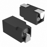
CAP ALUM ELECT 6.3V 10.0UF SMD

2222 085 63109

Manufacturer Part Number
2222 085 63109
Description
CAP ALUM ELECT 6.3V 10.0UF SMD
Manufacturer
Vishay
Series
085 CSr
Datasheet

Specifications of 2222 085 63109

Capacitance
10µF
Voltage Rating
6.3V
Tolerance
±20%
Lifetime @ Temp.
1500 Hrs @ 85°C
Operating Temperature
-40°C ~ 85°C
Features
General Purpose
Ripple Current
11mA
Esr (equivalent Series Resistance)
48.00 Ohm
Impedance
20 Ohm
Mounting Type
Surface Mount
Package / Case
Non-Standard SMD
Size / Dimension
0.346" L x 0.146" W (8.80mm x 3.70mm)
Height
0.154" (3.90mm)
Surface Mount Land Size
0.346" L x 0.146" W (8.80mm x 3.70mm)
Lead Free Status / RoHS Status
Contains lead / RoHS non-compliant
Lead Spacing
-
Other names
222208563109
BC1169TR
MAL208563109
MAL208563109E3
Document Number: 28300
Revision: 28-May-08
SELECTION CHART FOR C
QUICK REFERENCE DATA
DESCRIPTION
Nominal case sizes
(L x W x H in mm)
Rated capacitance range, C
Tolerance on C
Rated voltage range, U
Category temperature range
Endurance test at 85 °C
Useful life at 85 °C
Useful life at 40 °C;
1.4 x l
Shelf life at 0 V, 85 °C
Resistance to soldering
heat test
Based on sectional
specification
Climatic category IEC 60068
0.47
(µF)
1.0
2.2
3.3
4.7
6.8
C
10
15
22
R
R
applied
085 CS
11.9 x 3.7 x 3.9
8.8 x 3.7 x 3.9
R
6.3
-
-
-
-
-
-
-
Fig.1 Component outlines
R
longer
R
life
10 s at 260 °Cor 20 s at 215 °C
11.9 x 3.7 x 3.9
IEC 60384-18/CECC 32300
8.8 x 3.7 x 3.9
- 10 to + 50 % or ± 20 %
For technical questions, contact: aluminumcaps1@vishay.com
immersion in solder:
8.8 x 3.7 x 3.9 and
10
R
-
-
-
-
-
-
-
11.9 x 3.7 x 3.9
- 40 to + 85 °C
0.47 to 22 µF
40 000 hours
, U
1000 hours
1500 hours
139 CLL
6.3 to 63 V
500 hours
40/085/56
VALUE
Aluminum Capacitors
R
SMD (Chip) Standard
AND RELEVANT NOMINAL CASE SIZES (L x W x H in mm)
11.9 x 3.7 x 3.9
8.8 x 3.7 x 3.9
16
-
-
-
-
-
-
-
FEATURES
• Polarized
• SMD-version, rectangular case, insulated
• Miniaturized, high CV per unit volume, low height
• Flexible terminals, reflow and wave solderable
• Charge and discharge proof
• Supplied in blister tape on reel
APPLICATIONS
• SMD technology, boards with restricted mounting height
• General applications, consumer electronics, low profile
• Decoupling, smoothing, filtering and buffering
MARKING
The capacitors are marked (where possible) with the
following information:
• Rated capacitance (in µF)
• Rated voltage code (see Table 1), the U
• Name of manufacturer
• ‘-’ sign indicating the cathode. The anode is identified by
Examples for C
Table 1
U
RATED VOLTAGE MARKING CODE
U
Code letter
R
non-solid electrolyte, self healing
and lightweight equipment
indicates the position of the decimal point in the
capacitance value
bevelled edges
H22 represents 0.22 µF; 63 V
2G2 represents 2.2 µF; 40 V
22C represents 22 µF; 6.3 V
11.9 x 3.7 x 3.9
R
(V)
8.8 x 3.7 x 3.9
(V)
25
-
-
-
-
-
-
-
aluminum
R
6.3
; U
C
R
marking:
11.9 x 3.7 x 3.9
8.8 x 3.7 x 3.9
Vishay BCcomponents
10
D
electrolytic
40
-
-
-
-
-
-
-
16
E
25
capacitors,
F
11.9 x 3.7 x 3.9
11.9 x 3.7 x 3.9
8.8 x 3.7 x 3.9
8.8 x 3.7 x 3.9
www.vishay.com
R
085 CS
40
G
code letter
63
-
-
-
-
-
63
H
1

Related parts for 2222 085 63109

2222 085 63109 Summary of contents

Page 1

... Document Number: 28300 For technical questions, contact: aluminumcaps1@vishay.com Revision: 28-May-08 Aluminum Capacitors SMD (Chip) Standard FEATURES • Polarized non-solid electrolyte, self healing • SMD-version, rectangular case, insulated • Miniaturized, high CV per unit volume, low height • ...

Page 2

... reflow soldering solder land/ solder paste pattern Fig.3 Recommended pad dimensions for reflow and wave soldering www.vishay.com For technical questions, contact: aluminumcaps1@vishay.com 2 Aluminum Capacitors SMD (Chip) Standard 2 max. 3.9 2 max. max. 2.7 max. 3.9 4.1 max. max. Fig.2 Dimensional outlines ...

Page 3

... Fig.6 Maximum temperature load during vapor phase reflow soldering For technical questions, contact: aluminumcaps1@vishay.com Vishay BCcomponents ENSURE GOOD SOLDERING b c min. min. 12 6.8 15 6.8 MAX. EXPOSURE TIME ...

Page 4

... For technical questions, contact: aluminumcaps1@vishay.com 4 Aluminum Capacitors SMD (Chip) Standard 0 50 100 150 ORDERING EXAMPLE Electrolytic capacitor 085 series 10 µF/ 10 Nominal case size: 11.9 x 3.7 x 3.9 mm; Form BR ...

Page 5

... Curve 1: 6.3 V Curve 1: 6.3 V Curve Curve 0.6 Curve Curve 100 T (20 ° capacitance at 20 °C, 100 Hz amb 0 Fig.9 Typical multiplier of capacitance as a function of frequency For technical questions, contact: aluminumcaps1@vishay.com 085 CS Vishay BCcomponents VALUE ≤ 1. ≤ rev ≤ 0. µ ≤ 0.002 C ...

Page 6

... R Fig.10 Multiplier of useful life as a function of ambient temperature and ripple current load Table 8 MULTIPLIER OF RIPPLE CURRENT (I FREQUENCY (Hz) 50 100 300 1000 3000 ≥ 10 000 www.vishay.com For technical questions, contact: aluminumcaps1@vishay.com 6 Aluminum Capacitors SMD (Chip) Standard 3.3 3 3.1 R 3.0 2.8 2.6 2 ...

Page 7

... T amb 1500 hours = 85 °C; no voltage T amb applied; 500 hours after test minutes hours before measurement For technical questions, contact: aluminumcaps1@vishay.com 085 CS Vishay BCcomponents REQUIREMENTS ΔC/C: ± tan δ ≤ spec. limit ≤ spec. limit I L5 ΔC/C: ± applied; R tan δ ≤ spec. limit Z ≤ ...

Page 8

... Vishay disclaims any and all liability arising out of the use or application of any product described herein or of any information provided herein to the maximum extent permitted by law. The product specifications do not expand or otherwise modify Vishay’ ...

Related keywords