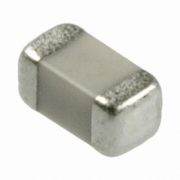
06035C821KAT2A AVX Corporation, 06035C821KAT2A Datasheet - Page 20

06035C821KAT2A
Manufacturer Part Number
06035C821KAT2A
Description
CAP CERM 820PF 10% 50V X7R 0603
Manufacturer
AVX Corporation
Specifications of 06035C821KAT2A
Capacitance
820pF
Package / Case
0603 (1608 Metric)
Voltage - Rated
50V
Tolerance
±10%
Temperature Coefficient
X7R
Mounting Type
Surface Mount, MLCC
Operating Temperature
-55°C ~ 125°C
Applications
General Purpose
Size / Dimension
0.063" L x 0.031" W (1.60mm x 0.80mm)
Thickness
0.90mm Max
Tolerance (+ Or -)
10%
Voltage
50VDC
Temp Coeff (dielectric)
X7R
Operating Temp Range
-55C to 125C
Mounting Style
Surface Mount
Construction
SMT Chip
Case Style
Ceramic Chip
Failure Rate
Not Required
Wire Form
Not Required
Product Length (mm)
1.6mm
Product Depth (mm)
0.81mm
Product Height (mm)
0.86mm
Product Diameter (mm)
Not Requiredmm
Voltage Rating
50 Volts
Operating Temperature Range
- 55 C to + 125 C
Temperature Coefficient / Code
X7R
Product
General Type MLCCs
Dimensions
0.81 mm W x 1.6 mm L x 0.860 mm H
Termination Style
SMD/SMT
Lead Free Status / RoHS Status
Lead free / RoHS Compliant
Features
-
Ratings
-
Lead Spacing
-
Lead Free Status / Rohs Status
Details
Other names
478-1214-2
Surface Mounting Guide
MLC Chip Capacitors
Solder Tip
Solder Tip
Preferred Method - No Direct Part Contact
Poor Method - Direct Contact with Part
PCB BOARD DESIGN
To avoid many of the handling problems, AVX recommends that MLCs be located at least .2" away from nearest edge of
board. However when this is not possible, AVX recommends that the panel be routed along the cut line, adjacent to where the
MLC is located.
No Stress Relief for MLCs
Routed Cut Line Relieves Stress on MLC
60


