RDEF51H223Z0K1C03B Murata Electronics North America, RDEF51H223Z0K1C03B Datasheet - Page 2
RDEF51H223Z0K1C03B
Manufacturer Part Number
RDEF51H223Z0K1C03B
Description
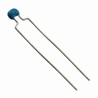
CAP CER 22000PF 50V Y5V RAD
Manufacturer
Murata Electronics North America
Series
RDEr
Datasheets
1.RPEF51H104Z2K1A03B.pdf
(2 pages)
2.RDEE41H104M0K1C03B.pdf
(3 pages)
3.RDEF51H223Z0K1C03B.pdf
(1 pages)
Specifications of RDEF51H223Z0K1C03B
Capacitance
0.022µF
Voltage - Rated
50V
Tolerance
-20%, +80%
Temperature Coefficient
Y5V (F)
Mounting Type
Through Hole
Operating Temperature
-30°C ~ 85°C
Applications
General Purpose
Package / Case
Radial
Size / Dimension
0.236" L x 0.158" W (6.00mm x 4.00mm)
Thickness
2.50mm Max
Lead Spacing
0.197" (5.00mm)
Lead Style
Flat Bent
Lead Free Status / RoHS Status
Lead free by exemption / RoHS Compliant
Features
-
Ratings
-
Other names
490-5398


No.
10
11 Solderability of Leads
12
RDE Series (Only for Commercial) Specifications and Test Methods
8
9
Continued from the preceding page.
Capacitance
Temperature
Characteristics
Terminal
Strength
Vibration
Resistance
Resistance
to
Soldering
Heat
Item
Capacitance
Change
Temperature
Coefficient
Capacitance
Drift
Tensile
Strength
Bending
Strength
Appearance No defects or abnormalities
Capacitance Within the specified tolerance
Q/D.F.
Appearance No defects or abnormalities
Capacitance
Change
Dielectric
Strength
(Between
Terminals)
Temperature Compensating Type High Dielectric Constant Type
Within the specified tolerance
(Table A on last column)
Within the specified tolerance
(Table A on last column)
Within 0.2% or 0.05pF
(whichever is larger)
Termination not to be broken or loosened
Termination not to be broken or loosened
30pF min.: QU1,000
30pF max.: QU400+20C
C: Nominal capacitance (pF)
Lead wire should be soldered with uniform coating on the axial
direction over 3/4 of the circumferential direction.
Within 2.5% or 0.25pF
(whichever is larger)
No defects
Specifications
Within the specified tolerance
(Table B on last column)
Char. X7R: 0.025 max.
Char. F, Y5V: 0.05 max.
Char. X7S: 0.125 max.
Char. X7R, X7S: Within 10%
Char. F, Y5V: Within 20%
The capacitance change should be measured after 5
min. at each specified temperature stage.
(1) Temperature Compensating Type
The temperature coefficient is determined using the
capacitance measured in step 3 as a reference. When
cycling the temperature sequentially from step 1
through 5 (-55 to +125˚C) the capacitance should be
within the specified tolerance for the temperature
coefficient and capacitance change as shown in Table
A. The capacitance drift is calculated by dividing the
differences between the maximum and minimum
measured values in step 1, 3 and 5 by the cap. value in
step 3.
(2) High Dielectric Constant Type
The ranges of capacitance change compared with the
25˚C (Char. F: 20˚C) value over the temperature
ranges as shown in Table B should be within the
specified ranges.
• Pretreatment (for high dielectric constant type)
Perform a heat treatment at 150+0/-10 C for 1 hr., and
then let sit at room temperature for 24 2 hrs.
As in the figure, fix the capacitor body, apply the force
gradually to each lead in the radial direction of the
capacitor until reaching 10N and then keep the force
applied for 10 1 sec.
Each lead wire should be subjected to a force of 2.5N
and then bent 90 at the point of egress in one
direction. Each wire is then returned to the original
position and bent 90 in the opposite direction at the
rate of one bend per 2 to 3 sec.
The capacitor is soldered securely to a supporting
terminal and a 10 to 55Hz vibration of 1.5mm peak-
peak amplitude is applied for 6 hrs. total, 2 hrs. in each
mutually perpendicular direction. Allow 1 min. to cycle
the frequency from 10Hz to 55Hz and the converse.
The terminal of a capacitor is dipped into a 25% ethanol
(JIS-K-8101) solution of rosin (JIS-K-5902) and
then into molten solder for 2 0.5 sec. In both cases the
depth of dipping is up to about 1.5mm to 2mm from the
terminal body.
Temp. of solder: 245 5˚C Lead Free Solder (Sn-3.0Ag-0.5Cu)
The lead wire is immersed in the melted solder 1.5mm
to 2mm from the main body at 350 10 C for 3.5 0.5
sec.
The specified items are measured after 24 2 hrs.
• Pretreatment (for high dielectric constant type)
Perform a heat treatment at 150+0/-10 C for 1 hr., and
then let sit at room temperature for 24 2 hrs.
Step
1
2
3
4
5
235 5˚C H60A or H63A Eutectic Solder
F
Test Method
Continued on the following page.
Temperature (˚C)
125 3
-55 3
25 2
25 2
25 2
Related parts for RDEF51H223Z0K1C03B
Image
Part Number
Description
Manufacturer
Datasheet
Request
R

Part Number:
Description:
BUZZER PIEZO 25VP-P SMD
Manufacturer:
Murata Electronics North America

Part Number:
Description:
CAP 4-ARRAY 680PF 100V X7R 1206
Manufacturer:
Murata Electronics North America
Datasheet:
Part Number:
Description:
CAP 4-ARRAY 1000PF 100V X7R 1206
Manufacturer:
Murata Electronics North America
Datasheet:
Part Number:
Description:
CAP 4-ARRAY 1800PF 100V X7R 1206
Manufacturer:
Murata Electronics North America
Datasheet:
Part Number:
Description:
CAP 4-ARRAY 68000PF 16V X7R 1206
Manufacturer:
Murata Electronics North America
Datasheet:

Part Number:
Description:
CAP CER 1000PF 50V 10% X7R 0402
Manufacturer:
Murata Electronics North America
Datasheet:
Part Number:
Description:
CAP CER 10000PF 16V 10% X7R 0402
Manufacturer:
Murata Electronics North America
Datasheet:

Part Number:
Description:
CAP 5.5-25PF 2.5X3.2MM SMD
Manufacturer:
Murata Electronics North America
Datasheet:

Part Number:
Description:
CAP 4.5-20PF 2.5X3.2MM SMD
Manufacturer:
Murata Electronics North America
Datasheet:

Part Number:
Description:
CAP 5.0-20PF 3.2X4.5MM SMD RED
Manufacturer:
Murata Electronics North America
Datasheet:

Part Number:
Description:
CAP 2.0-6.0PF 3.2X4.5MM SMD BLU
Manufacturer:
Murata Electronics North America
Datasheet:

Part Number:
Description:
CAP 1.4-3.0PF 3.2X4.5MM SMD BRN
Manufacturer:
Murata Electronics North America
Datasheet:

Part Number:
Description:
CAP 3.0-10PF 3.2X4.5MM SMD WHT
Manufacturer:
Murata Electronics North America
Datasheet:

Part Number:
Description:
CAP 2.0-6.0PF 4X4.5MM TOPADJ BLU
Manufacturer:
Murata Electronics North America
Datasheet:

Part Number:
Description:
CAP 8.5-40PF 4X4.5MM TOPADJ YEL
Manufacturer:
Murata Electronics North America
Datasheet: