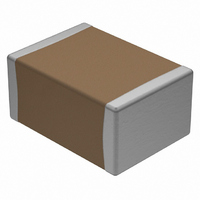
VJ1812Y223KXGAT Vishay, VJ1812Y223KXGAT Datasheet - Page 2

VJ1812Y223KXGAT
Manufacturer Part Number
VJ1812Y223KXGAT
Description
CAP CER .022UF10% 1000V X7R 1812
Manufacturer
Vishay
Series
VJr
Datasheet
1.VJ0603A470JXAAC.pdf
(14 pages)
Specifications of VJ1812Y223KXGAT
Capacitance
0.022µF
Voltage - Rated
1000V (1kV)
Tolerance
±10%
Temperature Coefficient
X7R
Mounting Type
Surface Mount, MLCC
Operating Temperature
-55°C ~ 125°C
Features
High Voltage
Applications
General Purpose
Package / Case
1812 (4532 Metric)
Size / Dimension
0.177" L x 0.126" W (4.50mm x 3.20mm)
Thickness
2.18mm Max
Dielectric Characteristic
X7R
Capacitance Tolerance
± 10%
Voltage Rating
1000VDC
Capacitor Case Style
1812
No. Of Pins
2
Capacitor Mounting
SMD
Rohs Compliant
Yes
Lead Free Status / RoHS Status
Lead free / RoHS Compliant
Ratings
-
Lead Spacing
-
Other names
720-1149-2
Available stocks
Company
Part Number
Manufacturer
Quantity
Price
Company:
Part Number:
VJ1812Y223KXGAT
Manufacturer:
Vishay
Quantity:
2 000
Note
• Detail ratings see selection chart
Notes
(1)
(2)
(3)
(4)
(5)
(6)
Document Number: 45199
Revision: 25-Jan-11
VJ0805
QUICK REFERENCE DATA
DIELECTRIC
C0G (NP0)
X5R
X7R
ORDERING INFORMATION
Selected values for X5R, see selection chart
Selected values available, contact
DC voltage rating should not be exceeded in application. Other application factors may affect the MLCC performance.
Consult for questions:
Process code may be added with up to three digits, used to control non-standard products and/or special requirements
Case size designator may be replaced by four digit drawing number used to control non-standard products and/or special requirements
Termination code “E” is for conductive epoxy assembly. Contact
CODE
CASE
0402
0603
0805
1206
1210
1808
1812
1825
2220
2225
3640
(3)
DIELECTRIC
G = X5R
A = C0G
Y = X7R
(NP0)
Y
(4)
mlcc@vishay.com
Surface Mount Multilayer Ceramic Chip Capacitors
NOMINAL CODE
CAPACITANCE
picofarads (pF).
significant, the
102 = 1000 pF
1R8 = 1.8 pF
Expressed in
The first two
Examples
multiplier.
digits are
third is a
102
mlcc@vishay.com
CASE
0402
0603
0805
1206
1210
1808
1812
1825
2220
2225
0805
0402
0603
0805
1206
1210
1808
1812
1825
2220
2225
3640
For technical questions, contact:
for Commercial Applications
F, G, J, K 10 pF
CAPACITANCE
B, C, D < 10 pF
C = ± 0.25 pF
B = ± 0.10 pF
TOLERANCE
D = ± 0.5 pF
M = ± 20 %
K = ± 10 %
C0G (NP0):
G = ± 2 %
F = ± 1 %
J = ± 5 %
X7R/X5R:
J, K, M
Note:
K
for list of released ratings
MAXIMUM VOLTAGE
100 % tin plated
100 % tin plated
TERMINATION
matte finish
X = Ni barrier
mlcc@vishay.com
B = Polymer
1000
1000
1000
1000
1000
1000
1000
1000
F, E = AgPd
matte finish
100
200
500
630
630
500
100
200
250
630
630
500
500
(V)
10
X
mlcc@vishay.com
(5)
G = 1000 V
RATING
VOLTAGE
B = 100 V
C = 200 V
P = 250 V
E = 500 V
L = 630 V
Q = 10 V
X = 25 V
A = 50 V
for availability
J = 16 V
DC
A
MINIMUM
(1)
VJ Commercial Series
100 pF
270 pF
270 pF
560 nF
120 pF
330 pF
330 pF
330 pF
390 pF
470 pF
1.0 pF
1.0 pF
1.0 pF
1.0 pF
1.0 nF
56 pF
18 pF
39 pF
10 nF
15 nF
33 nF
27 nF
M = Marked
available for
termination
MARKING
Unmarked
Marking is
1206 with
0805 and
code “X”
Note:
only
A =
A
CAPACITANCE
PACKAGING
Vishay Vitramon
I = 11 1/4"/13" reel/flamed
“I” and “O” are used for
T = 7" reel/plastic tape
C = 7" reel/paper tape
size 0402/0603/0805
R = 11 1/4"/13" reel/
P = 11 1/4"/13" reel/
“F”, “E” termination
O = 7" reel/flamed
T
plastic tape
paper tape
paper tape
paper tape
MAXIMUM
220 pF
820 pF
Note:
150 nF
470 nF
270 nF
3.9 nF
1.0 μF
1.0 μF
1.0 μF
1.5 μF
2.7 μF
2.2 μF
4.7 μF
6.8 μF
10 nF
22 nF
10 nF
22 nF
39 nF
47 nF
56 nF
47 nF
www.vishay.com
PROCESS
CODE
###
(2)
65


