TAJA225K006RNJ AVX Corporation, TAJA225K006RNJ Datasheet - Page 13
TAJA225K006RNJ
Manufacturer Part Number
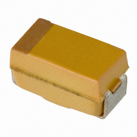
TAJA225K006RNJ
Description
CAP TANT 2.2UF 6.3V 10% SMD
Manufacturer
AVX Corporation
Series
TAJr
Type
Moldedr
Specifications of TAJA225K006RNJ
Capacitance
2.2µF
Package / Case
1206 (3216 Metric)
Voltage - Rated
6.3V
Tolerance
±10%
Operating Temperature
-55°C ~ 125°C
Mounting Type
Surface Mount
Size / Dimension
0.126" L x 0.063" W (3.20mm x 1.60mm)
Height
0.063" (1.60mm)
Manufacturer Size Code
A
Features
General Purpose
Tolerance (+ Or -)
10%
Voltage
6.3VDC
Esr
9Ohm
Mounting Style
Surface Mount
Polarity
Polar
Construction
SMT Chip
Case Style
Molded
Case Code
A
Lead Spacing (nom)
Not Requiredmm
Df
6%
Dcl
0.5uA
Seal
Not Required
Insulation
Not Required
Failure Rate
Not Required
Wire Form
Not Required
Product Length (mm)
3.2mm
Product Height (mm)
1.6mm
Product Depth (mm)
1.6mm
Product Diameter (mm)
Not Requiredmm
Seated Plane Height
Not Requiredmm
Length W/weld (max)
Not Requiredmm
Operating Temp Range
-55C to 125C
Lead Free Status / RoHS Status
Lead free / RoHS Compliant
Lead Spacing
-
Esr (equivalent Series Resistance)
-
Lead Free Status / RoHS Status
Compliant, Lead free / RoHS Compliant
Other names
TAJA225K006R
TAJA225K006R
TAJA225K006R


Technical Summary and
Application Guidelines
2.1 RIPPLE RATINGS (A.C.)
In an a.c. application heat is generated within the capacitor
by both the a.c. component of the signal (which will depend
upon the signal form, amplitude and frequency), and by the
d.c. leakage. For practical purposes the second factor is
insignificant. The actual power dissipated in the capacitor is
calculated using the formula:
and
and substituting
where
Maximum a.c. ripple voltage (E
From the previous equation:
SECTION 2
A.C. OPERATION, RIPPLE VOLTAGE AND RIPPLE CURRENT
Case
size
TAJ/TPS/CWR11/THJ
I = rms ripple current, amperes
R = equivalent series resistance, ohms
E = rms ripple voltage, volts
P = power dissipated, watts
Z = impedance, ohms, at frequency under
W
A
B
C
D
R
S
Y
E
T
V
Series Molded Chip
rearranged to I =
consideration
dissipation (W)
Max. power
E
0.075
0.085
0.110
0.150
0.165
0.055
0.065
0.080
0.250
0.090
0.125
max
P =
P = E
max
= Z
).
Table I: Power Dissipation Ratings (In Free Air)
Z
I
2
2
2
R
R
(
(
P
P
⁄
⁄
R
R
) .....(Eq. 1)
)
.....(Eq. 2)
Series Molded Chip
Case
size
A
B
C
D
G
H
E
F
TAZ/CWR09
dissipation (W)
Max. power
0.050
0.070
0.075
0.080
0.090
0.100
0.125
0.150
Where P is the maximum permissible power dissipated as
listed for the product under consideration (see tables).
However care must be taken to ensure that:
1. The d.c. working voltage of the capacitor must not be
2. The sum of the applied d.c. bias voltage and the negative
Historical ripple calculations.
Previous ripple current and voltage values were calculated
using an empirically derived power dissipation required to
give a 10°C rise of the capacitors body temperature from
room temperature, usually in free air. These values are shown
in Table I. Equation 1 then allows the maximum ripple current
to be established, and Equation 2, the maximum ripple
voltage. But as has been shown in the AVX article on thermal
management by I. Salisbury, the thermal conductivity of a
Tantalum chip capacitor varies considerably depending upon
how it is mounted.
exceeded by the sum of the positive peak of the applied
a.c. voltage and the d.c. bias voltage.
peak of the a.c. voltage must not allow a voltage reversal
in excess of the “Reverse Voltage”.
Temperature correction factor
TAJ/TPS/CWR11/THJ
Temp. °C
Series Molded Chip
+125
+25
+55
+85
for ripple current
TAZ/CWR09
Factor
1.0
0.95
0.90
0.40
41
Related parts for TAJA225K006RNJ
Image
Part Number
Description
Manufacturer
Datasheet
Request
R

Part Number:
Description:
Manufacturer:
AVX Corporation
Datasheet:
Part Number:
Description:
Manufacturer:
AVX Corporation
Datasheet:
Part Number:
Description:
Manufacturer:
AVX Corporation
Datasheet:
Part Number:
Description:
Manufacturer:
AVX Corporation
Datasheet:
Part Number:
Description:
Manufacturer:
AVX Corporation
Datasheet: