LLA219R71C683MA01L Murata Electronics North America, LLA219R71C683MA01L Datasheet - Page 141
LLA219R71C683MA01L
Manufacturer Part Number
LLA219R71C683MA01L
Description
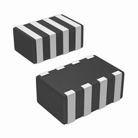
CAP CER 68000PF 16V X7R 0805
Manufacturer
Murata Electronics North America
Series
LLAr
Datasheets
1.GNM1M2R71E472MA01D.pdf
(4 pages)
2.GNM1M2R61A105ME14D.pdf
(221 pages)
3.LLL185R70J224MA01L.pdf
(4 pages)
Specifications of LLA219R71C683MA01L
Capacitance
0.068µF
Voltage - Rated
16V
Tolerance
±20%
Temperature Coefficient
X7R
Mounting Type
Surface Mount, MLCC
Operating Temperature
-55°C ~ 125°C
Features
Low ESL, Multi-Terminal
Applications
General Purpose
Package / Case
0805 (2012 Metric)
Size / Dimension
0.079" L x 0.049" W (2.00mm x 1.25mm)
Thickness
0.85mm
Lead Free Status / RoHS Status
Lead free / RoHS Compliant
Ratings
-
Lead Spacing
-
Other names
490-4413-2


!Note
• This PDF catalog is downloaded from the website of Murata Manufacturing co., ltd. Therefore, it’s specifications are subject to change or our products in it may be discontinued without advance notice. Please check with our
• This PDF catalog has only typical specifications because there is no space for detailed specifications. Therefore, please approve our product specifications or transact the approval sheet for product specifications before ordering.
sales representatives or product engineers before ordering.
!Note
4-2. Flow Soldering
1. When sudden heat is applied to the components, the
2. Excessively long soldering time or high soldering
3. When components are immersed in solvent after
4. Do not apply flow soldering to chips not listed in table 2.
Table 2
Recommended Conditions
5. Optimum Solder Amount for Flow Soldering
Preheating Peak Temperature
!Caution
Soldering Peak Temperature
Pb-Sn Solder: Sn-37Pb
Lead Free Solder: Sn-3.0Ag-0.5Cu
mechanical strength of the components will decrease
because a sudden temperature change causes
deformation inside the components. In order to prevent
mechanical damage in the components, preheating
should be required for both of the components and the
PCB board.
Preheating conditions are shown in table 2. It is required
to keep the temperature differential between the solder
and the component's surface ( T) as small as possible.
temperature can result in leaching of the outer electrodes,
causing poor adhesion or a reduction in capacitance
value due to loss of contact between electrodes and end
termination.
mounting, be sure to maintain the temperature difference
( T) between the component and solvent within the range
shown in the table 2.
5-1. The top of the solder fillet should be lower than the
Continued from the preceding page.
• Please read rating and !CAUTION (for storage, operating, rating, soldering, mounting and handling) in this catalog to prevent smoking and/or burning, etc.
• This catalog has only typical specifications because there is no space for detailed specifications. Therefore, please approve our product specifications or transact the approval sheet for product specifications before ordering.
thickness of components. If the solder amount is
excessive, the risk of cracking is higher during board
bending or any other stressful condition.
GRM18/21/31
LLL21/31
GQM18/21
Atmosphere
Part Number
Pb-Sn Solder
240 to 250 C
90 to 110 C
Air
Temperature Differential
TV150 C
Lead Free Solder
100 to 120 C
250 to 260 C
N
2
[Standard Conditions for Flow Soldering]
[Allowable Flow Soldering Temperature and Time]
Temperature (D)
Preheating
Peak
Temperature
Soldering
Peak
Temperature
In a case of repeated soldering, the accumulated
soldering time must be within the range shown above.
280
270
260
250
240
230
220
0
Adhesive
30-90 seconds
10
Preheating
T
20
Continued on the following page.
Soldering
5 seconds max.
Soldering Time (sec.)
30
Up to Chip Thickness
!Caution
Gradual
Cooling
Time
in section
40
139
C02E.pdf
10.12.20
Related parts for LLA219R71C683MA01L
Image
Part Number
Description
Manufacturer
Datasheet
Request
R

Part Number:
Description:
BUZZER PIEZO 25VP-P SMD
Manufacturer:
Murata Electronics North America

Part Number:
Description:
CAP 4-ARRAY 680PF 100V X7R 1206
Manufacturer:
Murata Electronics North America
Datasheet:
Part Number:
Description:
CAP 4-ARRAY 1000PF 100V X7R 1206
Manufacturer:
Murata Electronics North America
Datasheet:
Part Number:
Description:
CAP 4-ARRAY 1800PF 100V X7R 1206
Manufacturer:
Murata Electronics North America
Datasheet:
Part Number:
Description:
CAP 4-ARRAY 68000PF 16V X7R 1206
Manufacturer:
Murata Electronics North America
Datasheet:

Part Number:
Description:
CAP CER 1000PF 50V 10% X7R 0402
Manufacturer:
Murata Electronics North America
Datasheet:
Part Number:
Description:
CAP CER 10000PF 16V 10% X7R 0402
Manufacturer:
Murata Electronics North America
Datasheet:

Part Number:
Description:
CAP 5.5-25PF 2.5X3.2MM SMD
Manufacturer:
Murata Electronics North America
Datasheet:

Part Number:
Description:
CAP 4.5-20PF 2.5X3.2MM SMD
Manufacturer:
Murata Electronics North America
Datasheet:

Part Number:
Description:
CAP 5.0-20PF 3.2X4.5MM SMD RED
Manufacturer:
Murata Electronics North America
Datasheet:

Part Number:
Description:
CAP 2.0-6.0PF 3.2X4.5MM SMD BLU
Manufacturer:
Murata Electronics North America
Datasheet:

Part Number:
Description:
CAP 1.4-3.0PF 3.2X4.5MM SMD BRN
Manufacturer:
Murata Electronics North America
Datasheet:

Part Number:
Description:
CAP 3.0-10PF 3.2X4.5MM SMD WHT
Manufacturer:
Murata Electronics North America
Datasheet:

Part Number:
Description:
CAP 2.0-6.0PF 4X4.5MM TOPADJ BLU
Manufacturer:
Murata Electronics North America
Datasheet:

Part Number:
Description:
CAP 8.5-40PF 4X4.5MM TOPADJ YEL
Manufacturer:
Murata Electronics North America
Datasheet: